

Introduction: USB to ESP-01 Adapter Board Modification


Did you buy this USB to ESP-01 Adapter Board and found out that it can't be used for flashing the ESP-01? You're not alone. This first generation adapter doesn't have any mechanism to put the ESP-01 into Serial Programming mode which require pulling GPIO-0 pin LOW.
I found that very frustrating considering that this board is very cheap, small and convenient to be used to interface the ESP-01 to our PC. I have made another circuit on my breadboard along with FTDI adapter just to be able to flash ESP-01. Wouldn't it be nice if we can use this one instead?
One of the picture above shows the typical error message in Arduino IDE that we see when trying to flash the code to the ESP-01 without first putting it into serial programming mode.
In this Instructable I'm going to show you how to modify this adapter to be able to do just that with a simple mini tactile switch, and a little bit of soldering.
Lets get to it!
Step 1: Parts and Pinout
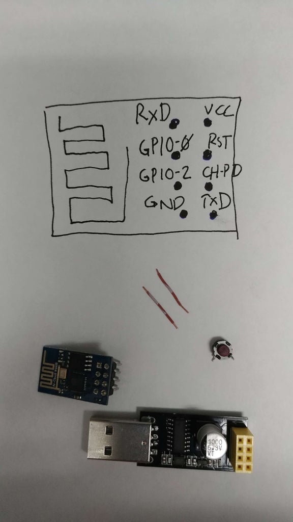

For this modification, I used a mini tactile switch that I salvaged from other electronic. You also need a couple of short wire to connect the switch to the board.
Step 2: Mounting and Soldering
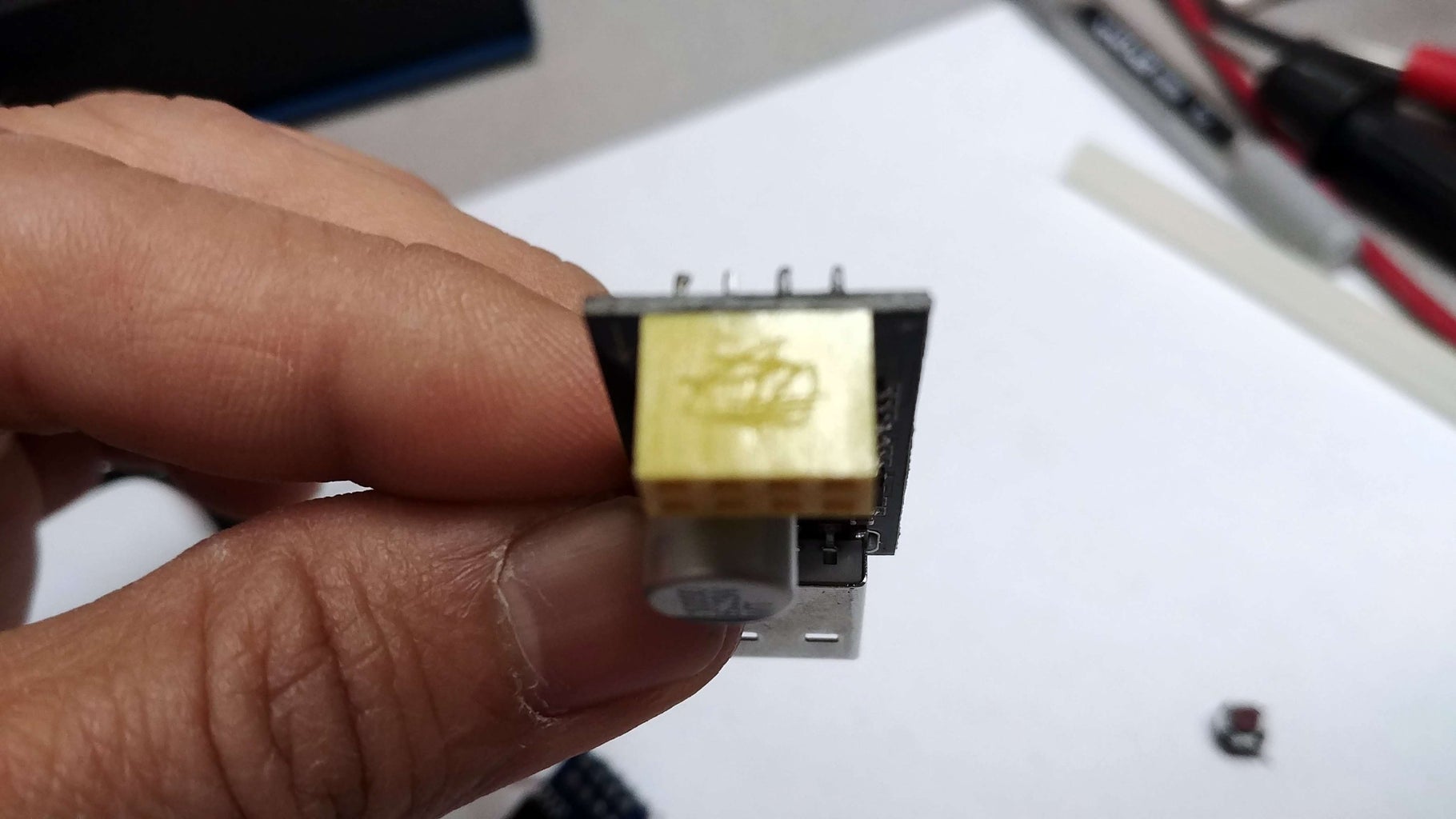


In this step we are going to mount the mini switch on to the back of the adapter's socket. I used hot glue for this, and optionally you can make a few scratches on the surface of the socket for better adhesion.
Once the glue is set, we're going to solder the 2 short wires between the switch and the GPIO-0 and GND pins. See above picture for the pins location.
This will effectively short the GPIO-0 and Ground when the switch is pressed.
Step 3: Flashing the ESP-01

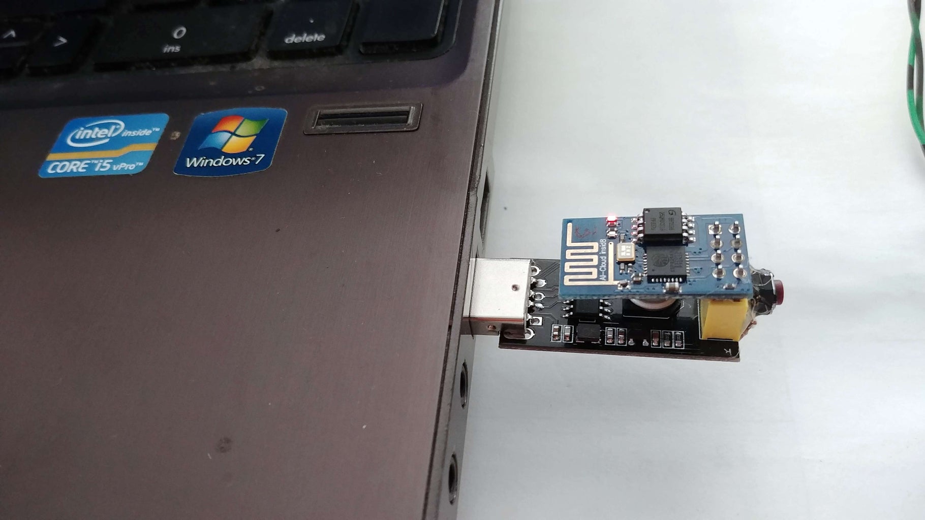


We're now done with our modification. To flash the ESP-01, follow the steps below:
1. Insert ESP-01 into the adapter's socket with the correct orientation shown in the picture.
2. While pressing the button of the tactile switch, insert the adapter into your PC's USB port. Release the button after about 1 sec. You'll be testing your finger's dexterity by doing this exercise.. :)
3. Set your Arduino IDE board setting, and upload your code. I've included the typical setting that works for ESP-01 board.
NOTES:
- Once the ESP-01 is flashed, we can use the adapter to power the ESP-01 from any USB power. It has built-in 10K pull-up resistors for GPIO-0 and GPIO-2 pins for it to do normal boot from flash.
- This adapter is based on CH340 chipset, in my PC it shows up as USB-SERIAL CH340
Enjoy..


