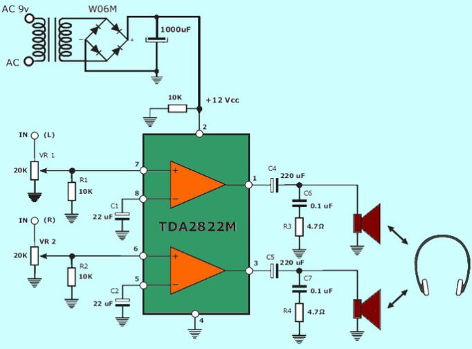
TDA2822M Low-Voltage Power Amplifier: Datasheet, Pinout and Circuit

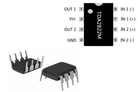
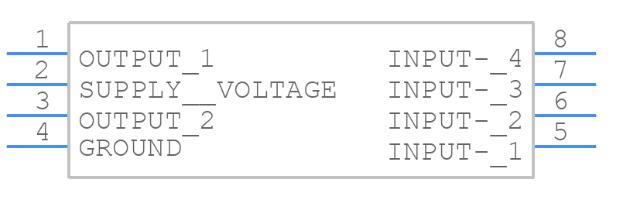
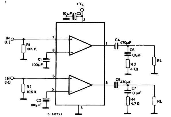
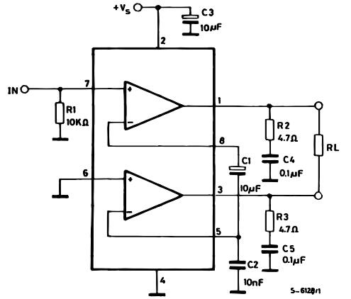
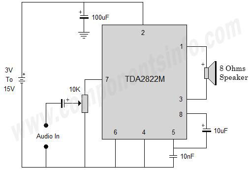
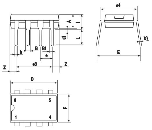
STMICROELECTRONICS TDA2822M Dual Low-Voltage Power Amplifier TDA2822M is a Dual low-voltage power amplifier. This post mainly covers the datasheet, power, circuit, pinout, replacement, and more details about the TDA2822M voltage amplifier. Furthermore, there is a huge range of semiconductors, capacitors, resistors, and ICs in stock. Welcome your RFQ!

Quick Links

TDA2822M Description

The TDA2822M is a Dual low-voltage power amplifier in an 8-Dip Minidip monolithic integrated circuit. It's designed to be used in portable tape players and radios as a dual audio power amplifier.

TDA2822M Pinout


Pin# Pin Name Pin Description
1 Output 1 Output 1 of the IC to   drive a speaker
2 Vcc Positive Supply   Connection of the IC
3 Output 2 Output 2 of the IC to   drive a speaker
4 Ground (GND) Ground / Negative For   Both Amplifiers
5 Input 2 (+) Inverting Input 2 of   the IC
6 Input 2 (-) Non-Inverting 2 Input   of IC
7 Input 1 (+) Non-Inverting Input 1   of IC
8 Input 2 (-) Inverting Input 1 of   the IC

TDA2822M CAD Model

TDA2822M Symbol


TDA2822M  Footprint


TDA2822M 3D Model

TDA2822M Schematics Diagram

TDA2822M Schematics Diagram

Specifications

STMicroelectronics TDA2822M technical specifications, attributes, parameters and parts with similar specifications to STMicroelectronics TDA2822M.

Product Attribute Attribute Value
Mount
Mounting Type
Package / Case
Number of Pins
Manufacturer Package Identifier
Operating Temperature
Packaging
JESD-609 Code
Pbfree Code
Part Status
Moisture Sensitivity Level (MSL)
Number of Terminations
ECCN Code
Type
Terminal Finish
Max Power Dissipation
Product Attribute Attribute Value
Voltage - Supply
Terminal Position
Number of Functions
Base Part Number
Pin Count
Output Type
Operating Supply Voltage
Supply Voltage-Max (Vsup)
Number of Channels
Nominal Supply Current
Power Dissipation
Output Current
Output Power
Supply Type
Bandwidth
Voltage Gain
Product Attribute Attribute Value
Power Supply Rejection Ratio (PSRR)
Gain
Max Output Power
Input Bias Current
Max Output Power x Channels @ Load
Harmonic Distortion
Load Impedance
Height
Length
Width
REACH SVHC
Radiation Hardening
RoHS Status
Lead Free

TDA2822M Features

  • Supply Voltage: 3-15V.

  • Output Power: 3.2 W.

  • Audio - Load Impedance: 8 Ohms.

  • Gain: 39 dB.

  • Operating Supply Current: 12 mA

  • Ib - Input Bias Current: 0.1 uA.

  • PSRR - Power Supply Rejection Ratio: 40 dB.

  • Available in 8-Pin DIP package

TDA2822M Circuit

TDA2822M Amplifier Test Circuit in Stereo Mode

Test Circuit in Stereo Mode

The left channel input is connected to the first built-in amplifier's non-inverting input (pin 1), while the right channel is connected to the second built-in amplifier's non-inverting input (pin 16). Separate 1000uF capacitors are used to link the inverting input of these built-in amplifiers to the ground (C5 and C6). Pins 6 and 11 of the IC control the amplified outputs (left and right). Capacitors C1 and C2 are used to connect the outputs to the matching speakers. The resistor-capacitor branch connected between speakers (0.1uF and 4.7 ohm) is intended to improve high-frequency stability and prevent oscillations. C7 is the power supply filter capacitor.


TDA2822M Amplifier Test Circuit in Bridge Mode

Test Circuit in Bridge Mode

The output power of the TDA2822M amplifier can be boosted by employing the bridge configuration in mono mode, as shown in Figure 2. The audio signal is fed into the first built-in amplifier's non-inverting input. The second built-in amplifier's non-inverting input is grounded. The C9, C11 capacitor branch grounds the inverting input of these amplifiers. The R5, C8, and R6, C10 branches are intended to improve high-frequency stability and reduce oscillations. C12 is a capacitor that filters the power source.


TDA2822M Applications

  • Audio amplifiers for radios

  • Computer Audio Amplifiers

  • Toys Audio Amplifiers

  • Battery Operated Music Players

  • Any Type of Low Power Audio Amplifier

  • TDA2822M Typical Application

How to Use TDA2822M

TDA2822M Circuit Diagram


The TDA2822M IC is used in the audio amplifier shown above. This is a mono audio amplifier circuit, but as previously stated, this IC can also be used to make a stereo amplifier circuit. With the IC, this circuit uses a few passive components. The operational voltage ranges between 3 and 15 volts DC. The 10K variable resistor will be connected to the audio input points specified in the design, which will be connected to the audio you want to amplify. A speaker with an impedance of 8 Ohms is connected between pins 1 and 3 of the IC.


For long-life performance, do not operate the IC at higher voltages than 15V, always protect the IC from short circuits, double-check the connection before applying power to the IC, do not apply more heat than the IC can handle while soldering, and make sure the IC is powered in the correct polarity or use a diode between the IC and the power supply. Always store and operate the IC at temperatures between -40 and +150 degrees Celsius.

TDA2822M Outline Dimensions

TDA2822M Outline Dimensions

TDA2822M Manufacturer

STMicroelectronics is a global independent semiconductor company and a leader in developing and delivering semiconductor solutions across the spectrum of microelectronics applications. An unrivaled combination of silicon and system expertise, manufacturing strength, Intellectual Property (IP) portfolio, and strategic partners’ positions, STMicroelectronics is at the forefront of System-on-Chip (SoC) technology and its products play a key role in enabling today's convergence trends.


Datasheet PDF

Documents

Download datasheets and manufacturer documentation for

Frequently Asked Questions

FAQ

What is the use of TDA2822M?
The TDA2822M is a monolithic integrated circuit in 8 lead Mini dip package. It is intended for use as a dual audio power amplifier in portable cassette players and radios.
What is the difference between TDA2822 and TDA2822M?
The package of TDA2822 is the same as TDA2822M. The difference is that: TDA2822M can work from 3V to 15V, while the highest working voltage of TDA2822 is only 8V. The higher the voltage, the higher the output power, so the output power of TDA2822M can be higher (dual-channel).
What is the working voltage of TDA2822M?
Power Supply Voltage Max: 15V    Power Supply Voltage Min: 1.8V
Can the integrated circuits TDA2822L and TDA2822M be directly replaced?
The working voltage of TDA2822L is 1.8-12V, and the working voltage of TDA2822M is 1.8-15V. The others are the same. They can be used interchangeably within the working voltage range. Your radio should be powered under 9V. It should be directly replaceable. Just look at the power supply voltage before changing.
Tags -
Share:

Comments

0 Comments