US3757635A - Multi-purpose munitions carrier - Google Patents
Multi-purpose munitions carrier Download PDFInfo
- Publication number
- US3757635A US3757635A US00127298A US3757635DA US3757635A US 3757635 A US3757635 A US 3757635A US 00127298 A US00127298 A US 00127298A US 3757635D A US3757635D A US 3757635DA US 3757635 A US3757635 A US 3757635A
- Authority
- US
- United States
- Prior art keywords
- carrier
- attachment means
- capsules
- munitions
- capsule
- Prior art date
- Legal status (The legal status is an assumption and is not a legal conclusion. Google has not performed a legal analysis and makes no representation as to the accuracy of the status listed.)
- Expired - Lifetime
Links
Images


Classifications
-
- F—MECHANICAL ENGINEERING; LIGHTING; HEATING; WEAPONS; BLASTING
- F41—WEAPONS
- F41H—ARMOUR; ARMOURED TURRETS; ARMOURED OR ARMED VEHICLES; MEANS OF ATTACK OR DEFENCE, e.g. CAMOUFLAGE, IN GENERAL
- F41H7/00—Armoured or armed vehicles
- F41H7/02—Land vehicles with enclosing armour, e.g. tanks
- F41H7/04—Armour construction
- F41H7/048—Vehicles having separate armoured compartments, e.g. modular armoured vehicles
-
- B—PERFORMING OPERATIONS; TRANSPORTING
- B62—LAND VEHICLES FOR TRAVELLING OTHERWISE THAN ON RAILS
- B62D—MOTOR VEHICLES; TRAILERS
- B62D55/00—Endless track vehicles
- B62D55/04—Endless track vehicles with tracks and alternative ground wheels, e.g. changeable from endless track vehicle into wheeled vehicle and vice versa
-
- F—MECHANICAL ENGINEERING; LIGHTING; HEATING; WEAPONS; BLASTING
- F41—WEAPONS
- F41A—FUNCTIONAL FEATURES OR DETAILS COMMON TO BOTH SMALLARMS AND ORDNANCE, e.g. CANNONS; MOUNTINGS FOR SMALLARMS OR ORDNANCE
- F41A23/00—Gun mountings, e.g. on vehicles; Disposition of guns on vehicles
- F41A23/20—Gun mountings, e.g. on vehicles; Disposition of guns on vehicles for disappearing guns
-
- F—MECHANICAL ENGINEERING; LIGHTING; HEATING; WEAPONS; BLASTING
- F41—WEAPONS
- F41H—ARMOUR; ARMOURED TURRETS; ARMOURED OR ARMED VEHICLES; MEANS OF ATTACK OR DEFENCE, e.g. CAMOUFLAGE, IN GENERAL
- F41H5/00—Armour; Armour plates
- F41H5/26—Peepholes; Windows; Loopholes
-
- F—MECHANICAL ENGINEERING; LIGHTING; HEATING; WEAPONS; BLASTING
- F41—WEAPONS
- F41H—ARMOUR; ARMOURED TURRETS; ARMOURED OR ARMED VEHICLES; MEANS OF ATTACK OR DEFENCE, e.g. CAMOUFLAGE, IN GENERAL
- F41H7/00—Armoured or armed vehicles
- F41H7/02—Land vehicles with enclosing armour, e.g. tanks
Definitions
- a multipurpose munitions carrier comprising: a basic automotive tracked vehicle having extendable arms, a central recess, and a first attachment means along the sides and edges of said recess; an interchangeable central assembly, said assembly insertable into said central recess and having a second attachment means, said second attachment means complementary and firmly securable to said first attachment means; and detachable personnel capsules, each of .said capsules rotatably attached individually to the end of said extendable arms of said tracked vehicle, and each capsule having independent control means whereby all functions of said multipurpose munitions carrier can be regulated by the operator of either capsule.
- the tank since its first appearance in military history, has always been in essence a sophisticated armored car.
- the armored car concept still prevails today, with most tanks requring a complement of four op erators, namely, the driver, the gunner, the loader and the commander.
- the thickness and weight of tank armor required to protect these personnel was forced to increase accordingly.
- the result of this progression is a main battle tank (hereinafter referred to as the MBT) that weighs approximately 60 tons. This tremendous weight has done much to limit the mobility and transportability of the modern MBT.
- the present invention which surmounts the various weight and mobility problems in the prior art, represents a new concept in tank design.
- This concept dispenses entirely with the armored car concept of a tank.
- a carrier system comprising three distinct subsystems is substituted. These subsystems are (1) a basic tracked vehicle, (2) a weapons or payload system, and (3) personnel capsules.
- Each personnel capsule is equipped with a control system capable of operating the total system with the other capsule knocked out. Since the gun and the engine compartment represent rather small targets, it becomes, as a practical matter, nearly impossible to knock out the present carrier with one hit. The consequence of this fact is that massive armor is no longer needed. One to two inch armor will generally suffice. However localized armor may be placed on more vulnerable components of the carrier such as the fuel tanks and the personnel capsules. Due to such a reduced use of armor, it becomes possible to construct a tank-like vehicle of about tons along theoretical lines that have not heretofore been explored.
- An object of this invention is to provide a combattype vehicle possessing increased mobility and effectiveness, and decreased weight and cost as compared with the conventional tank.
- Another object is to provide a combat-type vehicle whose mission capability can be changed through a substitution of interchangeable subsystems.
- 'A further object is to provide a tank-like vehicle which eliminates the conventional requirement of carrying all personnel within a central portion of the tank.
- Another object is to provide a tank-like vehicle that can be operated by a single operator.
- Yet another object of the present invention is to provide a tank-like vehicle that is light enough to be moved by a helicopter.
- Another object is to provide a tank-like vehicle that will protect its operators from chemical and radiological hazards.
- Still another object is to provide a vehicle whose consumption of fuel is below that of a conventional tank.
- the present invention comprises a basic automotive tracked vehicle having extendable arms, a central recess, and a first attachment means along the sides and edges of said recess; an interchangeable central assembly, said assembly insertable into said central recess and having a second attachment means, said second attachment means complementary and firmly securable to said first attachment means; and detachable personnel capsules, each of said capsules rotatably attached individually to the end of said extendable arms of said tracked vehicle, and each capsule having independent control means whereby all functions of said multipurpose munitions carrier can be regulated by the operator of either capsule.
- FIG. I is a sketch of the basic tracked vehicle with personnel capsules.
- FIG. 2 is a sketch of the Multi-Purpose Munitions Carrier (hereinafter referred to as the MMC) with a direct fire tank turret emplaced.
- MMC Multi-Purpose Munitions Carrier
- FIG. 3 is a front view of the MMC, illustrating its reduced frontal area as well as the rotating ability of the capsules.
- FIG. 4 is a sketch of the MMC traveling on a highway.
- FIG. 5 is a sketch of the MMC with an armored personnel carrier in place.
- FIG. 6 is a sketch of an MMC assembly station.
- FIG. 7A is a sketch of the MMC in combat.
- FIG. 7B is a second sketch of the MMC in combat.
- FIG. 8 is a sketch of the MMC fording a stream.
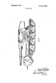
- FIG. 9 is a side view of the MMC with an artillery type (indirect fire) turret emplaced and the personnel capsules in a position that will allow for a 360 rotation of the turret.
- artillery type indirect fire
- the MMC comprises three basic subsystems, any of which can be readily replaced if it is damaged.
- the basic subsystems are: (l) a basic tracked vehicle possessing a tank chassis, (2) personnel capsules, and (3) interchangeable munitions assemblies.
- the interchangeable assemblies include a tank turret with an automatic loading capability, a personnel carn'er, a fuel carrier, a command vehicle, a missile launcher, a flame thrower, a mortar carrier, an anti-aircraft weapons carrier, a supply carrier and a crane carrier.
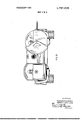
- FIG. 1 illustrates the basic tracked vehicle 12 with detachable personnel capsules 13.
- Each capsule has a plastic shield 14 underneath its steel cover 15.
- These capsules are each about five feet in diameter. Their weight can vary from 500 to 3,000 pounds each, depending on (1 the thickness of the armor used, and (2) the material of which the armor is composed. Usable materials include steel and hardened aluminum.
- Each personnel capsule is totally equipped with an independent cable-operated control system.
- This feature is of great importance since the presence of two personnel compartments, each a command center unto itself, and each fully protected against chemical and radiological combat environments, strongly challenges the presuppositions upon which all tank design has been predicated. More specifically, by utilizing the present inventive concept, the tank designer no longer has to be concerned with protecting a single large compartment, with the massive use of armor that such protection entails. Now, with the existence of two command centers in a single tank, much lighter armor on each will suffice, since a single hit will almost never be fatal to the entire MMC. In addition, once the feasibility of placing the tank operators outside of the tracked vehicle is recognized, a system possessing enormous flexibility and radically new battlefield capabilities becomes possible.
- FIG. 1 illustrates a set of metal rails 16 and 17 which serve as basic supports for each of the interchangeable assemblies.
- the rails are so spaced and designed so as to constitute secure attachment means which interlock into other complementary attachment means on each of the insertable interchangeable assemblies.
- An engine compartment 18 is provided with either a single or double engine.
- a double unit would provide a redundancy, thus enabling the MMC to operate with one engine shot out.
- FIG. 1 also illustrates two multihinged arms 19 and 20, each of which carries at its end a personnel capsule which can rotate on the end of the arm to which it is connected.
- These arms which can be suspended from either a front, central or rear point on the basic vehicle, possess a wide range of movement as is illustrated in FIGS. 1, 2, 7A, 7B, 8, and 9.
- the arms which are detachable, could be powered by any of several systems. These systems could be hydraulic, pneumatic or mechanical. A hydraulic (or other) pump system for the arms would operate off the carrier's engine. Movement of the arms is controlled through extendable steel cables with appropriate pulley configurations in the joints.
- FIG. 1 illustrates a drive sprocket wheel 21 and a road wheel mount 22. The sprocket wheel 21 powers the entire track system 23.
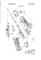
- FIG. 2 illustrates the MMC with a direct fire tank turret emplaced. Also, a personnel capsule with its armor shield emplaced is shown.
- FIG. 3 illustrates the low frontal profile of the MMC.
- a telescopic and retractable nose wheel 24, illustrated in FIG. 4, provides the vehicle with good maneuverability on roads. Braking is accomplished by the regular tank brakes.
- Road wheel mount 22 (see FIG. 1) provides a means by which rear wheels 26 can easily be attached or detached.
- FIG. 4 also illustrates an MMC equipped with a missile launcher.
- remote control operation of the personnel capsules is achieved through the use of heavy electrical wiring to the basic tracked vehicle and the interchangeable assemblies.
- remote control is achieved through heavy wiring to an automatic gun loading system in the turret.
- Such an automatic loading system is within the state of the art as described in Volume 10 of Army Research and Development News Magazine (December, 1969).
- FIG. is a side view of the MMC equipped with an armored personnel carrier interchangeable assembly.
- Complementary attachment means 28 is shown in profile on said interchangeable assembly. It is to be understood that any set of firmly securable complementary attachment means will suffice in place of attachment means 16 and 28.
- FIG. 6 illustrates an MMC assembly station. This station illustrates the flexibility of the MMC system. With an assembly station fully stocked with all the MMC subsystems, a tank Force Commander can quickly alter or tailor the weapons configuration of his command.
- the invention allows undamaged parts of knocked out MMC's to be quickly reassembled into effective weapons. Hence, a great portion of the equipment put out of action in a battle could be put back into action by reassembling the salvageable parts from each knocked out MMC.
- FIGS. 7A and 7B illustrate some further battlefield advantages of the MMC.
- the unique hiding ability of the personnel capsules is shown. Also, illustrated is the effectiveness of the elevated armored personnel capsules against distant snipers who could never otherwise be hit.
- the elevated capsules would also be invaluable in other terrains, such as a desert, where the horizon of the capsule operators would be more distant than that of an enemy.
- FIG. 8 shows the stream fording capability of the MMC.
- Each interchangeable assembly is water-tight and provided with a snorkel system that would permit submergence for several hours.
- the technology for such an intake and exhaust snorkel system was established by the German Tiger Royal tank which was used in World War II.
- FIG. 9 is a side view sketch of an MMC with the personnel capsules in a lowered front position that allows for a 360 rotation of an artillery type turret system. Said figure also illustrates a most important advantage of the MMC, namely, its low silhouette. This reduced profile makes the MMC hard to see and thus most difficult to hit. Also, the high mobility and hiding ability of the MMC render it a particularly elusive vehicle.
- the light weight of the MMC is also a critical consideration in combatting future concepts of aerial implanted mines. Such mines, while immobilizing a conventional tank force, would, in the case of a 15 ton MMC, merely require a helicopter lift out of the mined area.
- the cost of the MMC would be only about one-quarter that of the conventional MBT. Also, as aforenoted, only two rather than four operators are required. Actually, only one operator would be essential.
- the MMC can carry guns the equivalent in size to any on a 60 ton MBT.
- the firepower of such guns might normally thrust the center of gravity of a comparatively light vehicle too far to the rear.
- This potential problem is met by the use of hydraulic spades which descend from the rear of the tank and dig into the ground, thus providing support for the MMC when it is firing its heavy guns.
- a multipurpose munitions carrier comprising:
- a basic automotive tracked vehicle having extendable arms, a central recess, and a first attachment means along the sides and edges of said recess;
- each of said capsules rotatably attached individually to the end of said extendable arms of said tracked vehicle, and each capsule having independent control means whereby all functions of said multipurpose munitions carrier can be regulated by the operator of either capsule, said capsules including;
- a steel cover pivotally attached to said capsule sides for covering said transparent shield when said munitions carrier is under battle-field conditions.
Abstract
A multipurpose munitions carrier comprising: a basic automotive tracked vehicle having extendable arms, a central recess, and a first attachment means along the sides and edges of said recess; an interchangeable central assembly, said assembly insertable into said central recess and having a second attachment means, said second attachment means complementary and firmly securable to said first attachment means; and detachable personnel capsules, each of said capsules rotatably attached individually to the end of said extendable arms of said tracked vehicle, and each capsule having independent control means whereby all functions of said multipurpose munitions carrier can be regulated by the operator of either capsule.
Description
baited States Patent [1 1 Hiclterson et al.
1 Sept. 11, 1973 1 1 MULTl-PURPOSE MUNlTlONS CARRIER 22 Filed: Mar. 23, 1971 21 App1.No.: 127,298
[52] U.S. Cl. 89/36 H, 89/36 M [51] Int. Cl F4111 7/02 [58] Field of Search 89/36 H, 36 K, 36 L, 89/36 M, 37.5 A, 40 B, 40 C [56] References Cited UNITED STATES PATENTS 3,566,742 3/1971 Bemiss 89/40 B 2,404,256 7/1946 Tapp 89/36 M 1,334,794 3/1920 Rimailho 89/40 C 3,351,374 11/1967 Forsyth et a1... 89/36 H 1,317,103 9/1919 Rimailho 89/40 B 1,442,570 1/1923 l-Iolt t. 89/40 C 2,388,873 11/1945 Schwab 89/40 B FOREIGN PATENTS OR APPLICATIONS 683,549 10/1939 Germany 89/36 M 1,815,912 6/1970 Germany 89/3611 Primary Examiner-Stephen C. Bentley Att0rneyHarry M. Saragovitz, Edward J. Kelly and Herbert Berl 57 ABSTRACT A multipurpose munitions carrier comprising: a basic automotive tracked vehicle having extendable arms, a central recess, and a first attachment means along the sides and edges of said recess; an interchangeable central assembly, said assembly insertable into said central recess and having a second attachment means, said second attachment means complementary and firmly securable to said first attachment means; and detachable personnel capsules, each of .said capsules rotatably attached individually to the end of said extendable arms of said tracked vehicle, and each capsule having independent control means whereby all functions of said multipurpose munitions carrier can be regulated by the operator of either capsule.
5- Claims, 10 Drawing Figures PATENTED SEPI I I975 SHEET 1 BF 9 PATENTEDSEPI 1' ms SHEEI 2 BF 9 INVENTORS CK R.H|C J-MARH KERSON EFKA FRED ERI BY ANDREW xiii/4 WM PATENTEDSEP! i I975 3.7 57. 638
SHEET 3 0F 9 INVENTORS;
FREDERICK R. HICKERSON ANDREW J. MARHEFKA BY- My 7)). 4 J
amm- W itameys.
SHEET u 0F 9 FIG.4
g INVENTORS FREDERICK RHICKERSON ANDREW J. MARHEFKA PATENTED SEPI I I973 SHEEI 5 OF 9 INVENTORS,
FREDERICK R. HICKERSON BYI ANDREW J. MARHEFKA M fllforney PATENTED SEP] 1 I975 sum s 0F 9 INVENTORS A mw M E e K n CH r IR 0 HA R J w HE DRAW FRE BY AND PATENTED SEP] 1 I973 sum 7 BF R INVENTORfi,
FREDERICK R. HICKERSON ANDREW a. MARHEFKA PATENTEDSEP! 1191s SHEET 8 BF 9 INVENTORJ FREDERICK R. HICKERSON ANDREW d. MARHEFKA 8 Y W 997. XMM
4L1? 1M5 S W M flifornay mamm w H915 3.757. 636
SHEEI 9 0F 9 INVENTORS, FREDERICK R.H|CKERSON ANDREW J.MARHEFKA MULTI-PURPOSE MUNITIONS CARRIER The invention described herein may be manufactured, used and licensed by or for the Government for governmental purposes without the payment to us of any royalty thereon.
BACKGROUND OF THE INVENTION The tank, since its first appearance in military history, has always been in essence a sophisticated armored car. The armored car concept still prevails today, with most tanks requring a complement of four op erators, namely, the driver, the gunner, the loader and the commander. As the firepower of antitank weapons increased, the thickness and weight of tank armor required to protect these personnel was forced to increase accordingly. The result of this progression is a main battle tank (hereinafter referred to as the MBT) that weighs approximately 60 tons. This tremendous weight has done much to limit the mobility and transportability of the modern MBT.
It is to be further noted that all tanks have always been susceptible to being knocked out by a single hit. This weakness derives from the concentration of tank personnel in a single compartment.
The present invention, which surmounts the various weight and mobility problems in the prior art, represents a new concept in tank design. This concept dispenses entirely with the armored car concept of a tank. Instead, a carrier system comprising three distinct subsystems is substituted. These subsystems are (1) a basic tracked vehicle, (2) a weapons or payload system, and (3) personnel capsules. Each personnel capsule is equipped with a control system capable of operating the total system with the other capsule knocked out. Since the gun and the engine compartment represent rather small targets, it becomes, as a practical matter, nearly impossible to knock out the present carrier with one hit. The consequence of this fact is that massive armor is no longer needed. One to two inch armor will generally suffice. However localized armor may be placed on more vulnerable components of the carrier such as the fuel tanks and the personnel capsules. Due to such a reduced use of armor, it becomes possible to construct a tank-like vehicle of about tons along theoretical lines that have not heretofore been explored.
SUMMARY OF THE INVENTION An object of this invention is to provide a combattype vehicle possessing increased mobility and effectiveness, and decreased weight and cost as compared with the conventional tank.
Another object is to provide a combat-type vehicle whose mission capability can be changed through a substitution of interchangeable subsystems.
'A further object is to provide a tank-like vehicle which eliminates the conventional requirement of carrying all personnel within a central portion of the tank.
Another object is to provide a tank-like vehicle that can be operated by a single operator.
Yet another object of the present invention is to provide a tank-like vehicle that is light enough to be moved by a helicopter.
Another object is to provide a tank-like vehicle that will protect its operators from chemical and radiological hazards.
Still another object is to provide a vehicle whose consumption of fuel is below that of a conventional tank.
The present invention comprises a basic automotive tracked vehicle having extendable arms, a central recess, and a first attachment means along the sides and edges of said recess; an interchangeable central assembly, said assembly insertable into said central recess and having a second attachment means, said second attachment means complementary and firmly securable to said first attachment means; and detachable personnel capsules, each of said capsules rotatably attached individually to the end of said extendable arms of said tracked vehicle, and each capsule having independent control means whereby all functions of said multipurpose munitions carrier can be regulated by the operator of either capsule.
BRIEF DESCRIPTION OF THE DRAWINGS FIG. I is a sketch of the basic tracked vehicle with personnel capsules.
FIG. 2 is a sketch of the Multi-Purpose Munitions Carrier (hereinafter referred to as the MMC) with a direct fire tank turret emplaced.
FIG. 3 is a front view of the MMC, illustrating its reduced frontal area as well as the rotating ability of the capsules.
FIG. 4 is a sketch of the MMC traveling on a highway.
FIG. 5 is a sketch of the MMC with an armored personnel carrier in place.
FIG. 6 is a sketch of an MMC assembly station.
FIG. 7A is a sketch of the MMC in combat.
FIG. 7B is a second sketch of the MMC in combat.
FIG. 8 is a sketch of the MMC fording a stream.
FIG. 9 is a side view of the MMC with an artillery type (indirect fire) turret emplaced and the personnel capsules in a position that will allow for a 360 rotation of the turret.
DETAILED DESCRIPTION OF THE INVENTION The MMC comprises three basic subsystems, any of which can be readily replaced if it is damaged. The basic subsystems are: (l) a basic tracked vehicle possessing a tank chassis, (2) personnel capsules, and (3) interchangeable munitions assemblies. The interchangeable assemblies include a tank turret with an automatic loading capability, a personnel carn'er, a fuel carrier, a command vehicle, a missile launcher, a flame thrower, a mortar carrier, an anti-aircraft weapons carrier, a supply carrier and a crane carrier.
FIG. 1 illustrates the basic tracked vehicle 12 with detachable personnel capsules 13. Each capsule has a plastic shield 14 underneath its steel cover 15. These capsules are each about five feet in diameter. Their weight can vary from 500 to 3,000 pounds each, depending on (1 the thickness of the armor used, and (2) the material of which the armor is composed. Usable materials include steel and hardened aluminum.
Each personnel capsule, it is to be emphasized, is totally equipped with an independent cable-operated control system. This feature is of great importance since the presence of two personnel compartments, each a command center unto itself, and each fully protected against chemical and radiological combat environments, strongly challenges the presuppositions upon which all tank design has been predicated. More specifically, by utilizing the present inventive concept, the tank designer no longer has to be obsessed with protecting a single large compartment, with the massive use of armor that such protection entails. Now, with the existence of two command centers in a single tank, much lighter armor on each will suffice, since a single hit will almost never be fatal to the entire MMC. In addition, once the feasibility of placing the tank operators outside of the tracked vehicle is recognized, a system possessing enormous flexibility and radically new battlefield capabilities becomes possible.
This flexibility is evidenced in the easy convertability of the present carrier to entirely different missions through the use of interchangeable central assemblies.
FIG. 1 illustrates a set of metal rails 16 and 17 which serve as basic supports for each of the interchangeable assemblies. The rails are so spaced and designed so as to constitute secure attachment means which interlock into other complementary attachment means on each of the insertable interchangeable assemblies.
An engine compartment 18 is provided with either a single or double engine. A double unit would provide a redundancy, thus enabling the MMC to operate with one engine shot out.
FIG. 1 also illustrates two multihinged arms 19 and 20, each of which carries at its end a personnel capsule which can rotate on the end of the arm to which it is connected. These arms, which can be suspended from either a front, central or rear point on the basic vehicle, possess a wide range of movement as is illustrated in FIGS. 1, 2, 7A, 7B, 8, and 9. The arms, which are detachable, could be powered by any of several systems. These systems could be hydraulic, pneumatic or mechanical. A hydraulic (or other) pump system for the arms would operate off the carrier's engine. Movement of the arms is controlled through extendable steel cables with appropriate pulley configurations in the joints. In addition, FIG. 1 illustrates a drive sprocket wheel 21 and a road wheel mount 22. The sprocket wheel 21 powers the entire track system 23.
FIG. 2 illustrates the MMC with a direct fire tank turret emplaced. Also, a personnel capsule with its armor shield emplaced is shown.
FIG. 3 illustrates the low frontal profile of the MMC.
A telescopic and retractable nose wheel 24, illustrated in FIG. 4, provides the vehicle with good maneuverability on roads. Braking is accomplished by the regular tank brakes. Road wheel mount 22 (see FIG. 1) provides a means by which rear wheels 26 can easily be attached or detached. FIG. 4 also illustrates an MMC equipped with a missile launcher.
The remote control operation of the personnel capsules is achieved through the use of heavy electrical wiring to the basic tracked vehicle and the interchangeable assemblies. In the tank turret embodiment, remote control is achieved through heavy wiring to an automatic gun loading system in the turret. Such an automatic loading system is within the state of the art as described in Volume 10 of Army Research and Development News Magazine (December, 1969).
FIG. is a side view of the MMC equipped with an armored personnel carrier interchangeable assembly. Complementary attachment means 28 is shown in profile on said interchangeable assembly. It is to be understood that any set of firmly securable complementary attachment means will suffice in place of attachment means 16 and 28. I
FIG. 6 illustrates an MMC assembly station. This station illustrates the flexibility of the MMC system. With an assembly station fully stocked with all the MMC subsystems, a tank Force Commander can quickly alter or tailor the weapons configuration of his command.
This adaptability can of course be invaluable under battle conditions where the make-up of the enemy force may not be fully known. In short, a much higher degree of contingency planning becomes possible.
Also, the invention allows undamaged parts of knocked out MMC's to be quickly reassembled into effective weapons. Hence, a great portion of the equipment put out of action in a battle could be put back into action by reassembling the salvageable parts from each knocked out MMC.
FIGS. 7A and 7B illustrate some further battlefield advantages of the MMC. The unique hiding ability of the personnel capsules is shown. Also, illustrated is the effectiveness of the elevated armored personnel capsules against distant snipers who could never otherwise be hit. The elevated capsules would also be invaluable in other terrains, such as a desert, where the horizon of the capsule operators would be more distant than that of an enemy.
FIG. 8 shows the stream fording capability of the MMC. Each interchangeable assembly is water-tight and provided with a snorkel system that would permit submergence for several hours. The technology for such an intake and exhaust snorkel system was established by the German Tiger Royal tank which was used in World War II.
FIG. 9 is a side view sketch of an MMC with the personnel capsules in a lowered front position that allows for a 360 rotation of an artillery type turret system. Said figure also illustrates a most important advantage of the MMC, namely, its low silhouette. This reduced profile makes the MMC hard to see and thus most difficult to hit. Also, the high mobility and hiding ability of the MMC render it a particularly elusive vehicle.
The light weight of the MMC is also a critical consideration in combatting future concepts of aerial implanted mines. Such mines, while immobilizing a conventional tank force, would, in the case of a 15 ton MMC, merely require a helicopter lift out of the mined area.
In addition, the cost of the MMC would be only about one-quarter that of the conventional MBT. Also, as aforenoted, only two rather than four operators are required. Actually, only one operator would be essential.
Finally, it must be noted that the MMC can carry guns the equivalent in size to any on a 60 ton MBT. The firepower of such guns might normally thrust the center of gravity of a comparatively light vehicle too far to the rear. This potential problem is met by the use of hydraulic spades which descend from the rear of the tank and dig into the ground, thus providing support for the MMC when it is firing its heavy guns.
It is thus seen that the objects set forth above are among those made apparent from, and efficiently attained by, the preceding description. It is believed that the present invention 's attainment of these objects may be of tactical and strategic importance to the security of the United States and its allies.
' We wish it to be understood that we do not desire to be limited to the exact detail'of construction shown and described for obvious modification will occur to persons skilled in the art.
Having described our invention, what we claim as new, useful and non-obvious, and thus desire to secure by Letters Patent of the United States is:
l.' A multipurpose munitions carrier comprising:
a basic automotive tracked vehicle having extendable arms, a central recess, and a first attachment means along the sides and edges of said recess;
an interchangeable central assembly, said assembly insertable into said central recess and having a second attachment means, said second attachment means complementary and firmly securable to said first attachment means; and
detachable personnel capsules, each of said capsules rotatably attached individually to the end of said extendable arms of said tracked vehicle, and each capsule having independent control means whereby all functions of said multipurpose munitions carrier can be regulated by the operator of either capsule, said capsules including;
a plastic transparent shield covering each of said capsules upper sections; and
a steel cover pivotally attached to said capsule sides for covering said transparent shield when said munitions carrier is under battle-field conditions.
2. The munitions carrier in claim 1 wherein said interchangeable central assembly comprises a tank turret equipped with a remote electrical cable-controlled shell loading system.
3. The munitions carrier in claim 1 wherein said interchangeable central assembly comprises a personnel carrier.
4. The munitions carrier in claim l-wherein said interchangeable central assembly comprises a missile launcher.
5. The munitions carrier in claim R wherein said basic automotive tracked vehicle possesses an armored tank chassis.
Claims (5)
1. A multipurpose munitions carrier comprising: a basic automotive tracked vehicle having extendable arms, a central recess, and a first attachment means along the sides and edges of said recess; an interchangeable central assembly, said assembly insertable into said central recess and having a second attachment means, said second attachment means complementary and firmly securable to said first attachment means; and detachable personnel capsules, each of said capsules rotatably attached individually to the end of said extendable arms of said tracked vehicle, and each capsule having independent control means whereby all functions of said multipurpose munitions carrier can be regulated by the operator of either capsule, said capsules including; a plastic transparent shield covering each of said capsules upper sections; and a steel cover pivotally attached to said capsule sides for covering said transparent shield when said munitions carrier is under battle-field condiTions.
2. The munitions carrier in claim 1 wherein said interchangeable central assembly comprises a tank turret equipped with a remote electrical cable-controlled shell loading system.
3. The munitions carrier in claim 1 wherein said interchangeable central assembly comprises a personnel carrier.
4. The munitions carrier in claim 1 wherein said interchangeable central assembly comprises a missile launcher.
5. The munitions carrier in claim 1 wherein said basic automotive tracked vehicle possesses an armored tank chassis.
Applications Claiming Priority (1)
| Application Number | Priority Date | Filing Date | Title |
|---|---|---|---|
| US12729871A | 1971-03-23 | 1971-03-23 |
Publications (1)
| Publication Number | Publication Date |
|---|---|
| US3757635A true US3757635A (en) | 1973-09-11 |
Family
ID=22429371
Family Applications (1)
| Application Number | Title | Priority Date | Filing Date |
|---|---|---|---|
| US00127298A Expired - Lifetime US3757635A (en) | 1971-03-23 | 1971-03-23 | Multi-purpose munitions carrier |
Country Status (1)
| Country | Link |
|---|---|
| US (1) | US3757635A (en) |
Cited By (45)
| Publication number | Priority date | Publication date | Assignee | Title |
|---|---|---|---|---|
| DE2456732A1 (en) * | 1974-11-30 | 1976-08-12 | Precitronic | Rocket launcher for different types of rockets - with extendable observation mast for detecting low flying concealed helicopters |
| US4004494A (en) * | 1974-03-06 | 1977-01-25 | Etat Francais | Military observation post |
| DE2622995A1 (en) * | 1976-05-22 | 1977-12-01 | Systemtechnik Gmbh | Elevating chamber for low profile armoured vehicle - has hydraulic extending arm for raising to wide observation and firing position |
| JPS53151300U (en) * | 1977-05-04 | 1978-11-28 | ||
| DE3120338A1 (en) * | 1981-05-22 | 1982-12-09 | Eisenwerke Kaiserslautern Entwicklungsgesellschaft mbH, 6750 Kaiserslautern | Vehicle with lifting platform |
| EP0082127A2 (en) * | 1981-12-16 | 1983-06-22 | AB Hägglund & Söner | Station for a crew member in a combat vehicle |
| US4583444A (en) * | 1983-12-05 | 1986-04-22 | Ex-Cell-O Corporation | Armored vehicle with rotatable swing-away turret |
| FR2586627A1 (en) * | 1985-09-04 | 1987-03-06 | Privat Aime | Safety method and device for transporting valuables |
| FR2590851A1 (en) * | 1985-12-02 | 1987-06-05 | Privat Aime | Improved vehicle for transporting valuables and its control assembly |
| EP0244124A1 (en) * | 1986-05-02 | 1987-11-04 | Vickers Public Limited Company | Armoured vehicle with crane |
| EP0388762A2 (en) * | 1989-03-22 | 1990-09-26 | EISENWERKE KAISERSLAUTERN GmbH | Weapon module for tanks |
| US5129308A (en) * | 1989-03-21 | 1992-07-14 | Fuereder Georg F | Combat vehicle with extendible combat platform |
| AT400901B (en) * | 1989-09-25 | 1996-04-25 | Fuereder Georg | MILITARY COMBAT VEHICLE WITH AT LEAST TWO UNMANNED COMBAT PLATFORMS |
| DE19502036A1 (en) * | 1995-01-24 | 1996-07-25 | Krauss Maffei Ag | Caterpillar |
| WO1997028039A1 (en) * | 1996-01-30 | 1997-08-07 | Hägglunds Vehicle Ab | Tracked vehicle |
| DE10144366A1 (en) * | 2001-09-10 | 2003-03-27 | Rheinmetall Landsysteme Gmbh | Container adapter for an armored transport vehicle |
| EP1318375A3 (en) * | 2001-12-07 | 2003-06-18 | Rheinmetall Landsysteme GmbH | Manhole cover for a multifunctional mounting ring in armoured vehicles |
| US6584881B1 (en) | 2001-03-26 | 2003-07-01 | United Defense Lp | Multi-purpose missile launcher system for a military land vehicle |
| US6733227B2 (en) | 2002-02-21 | 2004-05-11 | Engineered Support Systems, Inc. | Elevating lift |
| US20050011348A1 (en) * | 2001-11-29 | 2005-01-20 | Ludovic Bertrand | Observation and/or firing system |
| US20060005695A1 (en) * | 2002-07-23 | 2006-01-12 | Michael Honlinger | Armoured wheeled vehicle consisting of individual sections |
| EP1717540A1 (en) * | 2005-04-29 | 2006-11-02 | Constructions Industrielles De La Mediterranee- Cnim | Military vehicle provided with a mobile turret |
| US7478580B1 (en) * | 2005-12-20 | 2009-01-20 | The United States Of America As Represented By The Secretary Of The Army | Sculpted transparent armor |
| US20100071540A1 (en) * | 2008-09-24 | 2010-03-25 | Nexter Systems | Retractable Light Turret |
| US20100163330A1 (en) * | 2008-12-29 | 2010-07-01 | Halliday Donald R | Deformable Modular Armored Combat System |
| US7845440B2 (en) | 2006-11-13 | 2010-12-07 | Raytheon Sarcos, Llc | Serpentine robotic crawler |
| US20110144828A1 (en) * | 2009-12-11 | 2011-06-16 | The Boeing Company | Unmanned Multi-Purpose Ground Vehicle with Different Levels of Control |
| US8002365B2 (en) | 2006-11-13 | 2011-08-23 | Raytheon Company | Conformable track assembly for a robotic crawler |
| US8002716B2 (en) | 2007-05-07 | 2011-08-23 | Raytheon Company | Method for manufacturing a complex structure |
| US8042630B2 (en) | 2006-11-13 | 2011-10-25 | Raytheon Company | Serpentine robotic crawler |
| US8185241B2 (en) | 2006-11-13 | 2012-05-22 | Raytheon Company | Tracked robotic crawler having a moveable arm |
| US8317555B2 (en) | 2009-06-11 | 2012-11-27 | Raytheon Company | Amphibious robotic crawler |
| US8392036B2 (en) | 2009-01-08 | 2013-03-05 | Raytheon Company | Point and go navigation system and method |
| US8393422B1 (en) | 2012-05-25 | 2013-03-12 | Raytheon Company | Serpentine robotic crawler |
| US8571711B2 (en) | 2007-07-10 | 2013-10-29 | Raytheon Company | Modular robotic crawler |
| US8935014B2 (en) | 2009-06-11 | 2015-01-13 | Sarcos, Lc | Method and system for deploying a surveillance network |
| US9031698B2 (en) | 2012-10-31 | 2015-05-12 | Sarcos Lc | Serpentine robotic crawler |
| CN103791776B (en) * | 2014-02-18 | 2015-10-28 | 沈阳陆胜机械有限公司 | Vehicular weapons bracket |
| US9409292B2 (en) | 2013-09-13 | 2016-08-09 | Sarcos Lc | Serpentine robotic crawler for performing dexterous operations |
| US9566711B2 (en) | 2014-03-04 | 2017-02-14 | Sarcos Lc | Coordinated robotic control |
| EP2390613B1 (en) | 2010-05-26 | 2017-03-29 | Leonardo S.P.A. | Robotized arm for a vehicle |
| RU2624126C1 (en) * | 2016-05-10 | 2017-06-30 | Владислав Александрович Полушкин | Method of lifting and displacement of loads in space |
| CN107131789A (en) * | 2017-07-11 | 2017-09-05 | 沈阳陆胜机械有限公司 | High stability vehicular weapons bracket |
| WO2018052484A1 (en) * | 2016-09-14 | 2018-03-22 | Raytheon Company | Robot arm launching system |
| USD1010504S1 (en) * | 2020-10-28 | 2024-01-09 | Milrem As | Universal modular unmanned hybrid vehicle |
Citations (9)
| Publication number | Priority date | Publication date | Assignee | Title |
|---|---|---|---|---|
| US1317103A (en) * | 1919-09-23 | Emile rimailho | ||
| US1334794A (en) * | 1918-08-08 | 1920-03-23 | Cie Forges Et Acieries Marine | Caterpillar gun-carriage |
| US1442570A (en) * | 1918-05-22 | 1923-01-16 | Holt Mfg Co | Detachable tractor unit for gun mounts |
| DE683549C (en) * | 1938-01-30 | 1939-11-08 | Georg Seitz Jr | Armored car with a combat and observation tower |
| US2388873A (en) * | 1942-02-09 | 1945-11-13 | Martin C Schwab | Combat vehicle |
| US2404256A (en) * | 1937-08-04 | 1946-07-16 | Tapp Ernest Thomas James | Mechanically propelled vehicle |
| US3351374A (en) * | 1963-07-01 | 1967-11-07 | Lockheed Aircraft Corp | Armor construction |
| DE1815912A1 (en) * | 1968-12-20 | 1970-06-25 | Otto Korf | Armored personnel carriers |
| US3566742A (en) * | 1969-08-27 | 1971-03-02 | Cadillac Gage Co | Armored vehicle having means for interchangeability top mounted weaponry |
-
1971
- 1971-03-23 US US00127298A patent/US3757635A/en not_active Expired - Lifetime
Patent Citations (9)
| Publication number | Priority date | Publication date | Assignee | Title |
|---|---|---|---|---|
| US1317103A (en) * | 1919-09-23 | Emile rimailho | ||
| US1442570A (en) * | 1918-05-22 | 1923-01-16 | Holt Mfg Co | Detachable tractor unit for gun mounts |
| US1334794A (en) * | 1918-08-08 | 1920-03-23 | Cie Forges Et Acieries Marine | Caterpillar gun-carriage |
| US2404256A (en) * | 1937-08-04 | 1946-07-16 | Tapp Ernest Thomas James | Mechanically propelled vehicle |
| DE683549C (en) * | 1938-01-30 | 1939-11-08 | Georg Seitz Jr | Armored car with a combat and observation tower |
| US2388873A (en) * | 1942-02-09 | 1945-11-13 | Martin C Schwab | Combat vehicle |
| US3351374A (en) * | 1963-07-01 | 1967-11-07 | Lockheed Aircraft Corp | Armor construction |
| DE1815912A1 (en) * | 1968-12-20 | 1970-06-25 | Otto Korf | Armored personnel carriers |
| US3566742A (en) * | 1969-08-27 | 1971-03-02 | Cadillac Gage Co | Armored vehicle having means for interchangeability top mounted weaponry |
Cited By (62)
| Publication number | Priority date | Publication date | Assignee | Title |
|---|---|---|---|---|
| US4004494A (en) * | 1974-03-06 | 1977-01-25 | Etat Francais | Military observation post |
| DE2456732A1 (en) * | 1974-11-30 | 1976-08-12 | Precitronic | Rocket launcher for different types of rockets - with extendable observation mast for detecting low flying concealed helicopters |
| DE2622995A1 (en) * | 1976-05-22 | 1977-12-01 | Systemtechnik Gmbh | Elevating chamber for low profile armoured vehicle - has hydraulic extending arm for raising to wide observation and firing position |
| JPS53151300U (en) * | 1977-05-04 | 1978-11-28 | ||
| DE3120338A1 (en) * | 1981-05-22 | 1982-12-09 | Eisenwerke Kaiserslautern Entwicklungsgesellschaft mbH, 6750 Kaiserslautern | Vehicle with lifting platform |
| EP0082127A3 (en) * | 1981-12-16 | 1983-12-14 | Ab Hagglund & Soner | Station for a crew member in a combat vehicle |
| EP0082127A2 (en) * | 1981-12-16 | 1983-06-22 | AB Hägglund & Söner | Station for a crew member in a combat vehicle |
| US4583444A (en) * | 1983-12-05 | 1986-04-22 | Ex-Cell-O Corporation | Armored vehicle with rotatable swing-away turret |
| FR2586627A1 (en) * | 1985-09-04 | 1987-03-06 | Privat Aime | Safety method and device for transporting valuables |
| FR2590851A1 (en) * | 1985-12-02 | 1987-06-05 | Privat Aime | Improved vehicle for transporting valuables and its control assembly |
| EP0244124A1 (en) * | 1986-05-02 | 1987-11-04 | Vickers Public Limited Company | Armoured vehicle with crane |
| US5129308A (en) * | 1989-03-21 | 1992-07-14 | Fuereder Georg F | Combat vehicle with extendible combat platform |
| EP0388762A2 (en) * | 1989-03-22 | 1990-09-26 | EISENWERKE KAISERSLAUTERN GmbH | Weapon module for tanks |
| EP0388762A3 (en) * | 1989-03-22 | 1991-09-18 | EISENWERKE KAISERSLAUTERN GmbH | Weapon module for tanks |
| AT400901B (en) * | 1989-09-25 | 1996-04-25 | Fuereder Georg | MILITARY COMBAT VEHICLE WITH AT LEAST TWO UNMANNED COMBAT PLATFORMS |
| EP0723905A1 (en) * | 1995-01-24 | 1996-07-31 | Krauss-Maffei Aktiengesellschaft | Tracked vehicle |
| WO1996022909A1 (en) * | 1995-01-24 | 1996-08-01 | Krauss-Maffei Ag | Caterpillar vehicle |
| DE19502036A1 (en) * | 1995-01-24 | 1996-07-25 | Krauss Maffei Ag | Caterpillar |
| WO1997028039A1 (en) * | 1996-01-30 | 1997-08-07 | Hägglunds Vehicle Ab | Tracked vehicle |
| US6000485A (en) * | 1996-01-30 | 1999-12-14 | Hagglunds Vechicle Ab | Tracked vehicle |
| US6584881B1 (en) | 2001-03-26 | 2003-07-01 | United Defense Lp | Multi-purpose missile launcher system for a military land vehicle |
| US6691600B2 (en) | 2001-03-26 | 2004-02-17 | United Defense, L.P. | Multi-purpose missile launcher system for a military land vehicle |
| DE10144366A1 (en) * | 2001-09-10 | 2003-03-27 | Rheinmetall Landsysteme Gmbh | Container adapter for an armored transport vehicle |
| US20050011348A1 (en) * | 2001-11-29 | 2005-01-20 | Ludovic Bertrand | Observation and/or firing system |
| EP1318375A3 (en) * | 2001-12-07 | 2003-06-18 | Rheinmetall Landsysteme GmbH | Manhole cover for a multifunctional mounting ring in armoured vehicles |
| US6733227B2 (en) | 2002-02-21 | 2004-05-11 | Engineered Support Systems, Inc. | Elevating lift |
| US20060005695A1 (en) * | 2002-07-23 | 2006-01-12 | Michael Honlinger | Armoured wheeled vehicle consisting of individual sections |
| EP1717540A1 (en) * | 2005-04-29 | 2006-11-02 | Constructions Industrielles De La Mediterranee- Cnim | Military vehicle provided with a mobile turret |
| US20060283316A1 (en) * | 2005-04-29 | 2006-12-21 | Elisabeth Richeux | Military vehicle comprising a swinging arm |
| US7624670B2 (en) * | 2005-04-29 | 2009-12-01 | Constructions Industrielles De La Mediterranee - Cnim | Military vehicle comprising a swinging arm |
| US7478580B1 (en) * | 2005-12-20 | 2009-01-20 | The United States Of America As Represented By The Secretary Of The Army | Sculpted transparent armor |
| US8042630B2 (en) | 2006-11-13 | 2011-10-25 | Raytheon Company | Serpentine robotic crawler |
| US8205695B2 (en) | 2006-11-13 | 2012-06-26 | Raytheon Company | Conformable track assembly for a robotic crawler |
| US7845440B2 (en) | 2006-11-13 | 2010-12-07 | Raytheon Sarcos, Llc | Serpentine robotic crawler |
| US8185241B2 (en) | 2006-11-13 | 2012-05-22 | Raytheon Company | Tracked robotic crawler having a moveable arm |
| US8002365B2 (en) | 2006-11-13 | 2011-08-23 | Raytheon Company | Conformable track assembly for a robotic crawler |
| US8434208B2 (en) | 2007-05-07 | 2013-05-07 | Raytheon Company | Two-dimensional layout for use in a complex structure |
| US8002716B2 (en) | 2007-05-07 | 2011-08-23 | Raytheon Company | Method for manufacturing a complex structure |
| US8571711B2 (en) | 2007-07-10 | 2013-10-29 | Raytheon Company | Modular robotic crawler |
| US8393258B2 (en) * | 2008-09-24 | 2013-03-12 | Nexter Systems | Retractable turret |
| US20100071540A1 (en) * | 2008-09-24 | 2010-03-25 | Nexter Systems | Retractable Light Turret |
| US8205703B2 (en) * | 2008-12-29 | 2012-06-26 | Hal-Tech Limited | Deformable modular armored combat system |
| US20100163330A1 (en) * | 2008-12-29 | 2010-07-01 | Halliday Donald R | Deformable Modular Armored Combat System |
| AU2009345804B2 (en) * | 2008-12-29 | 2016-03-03 | Hal-Tech Limited | Deformable modular armored combat system |
| US8392036B2 (en) | 2009-01-08 | 2013-03-05 | Raytheon Company | Point and go navigation system and method |
| US8317555B2 (en) | 2009-06-11 | 2012-11-27 | Raytheon Company | Amphibious robotic crawler |
| US8935014B2 (en) | 2009-06-11 | 2015-01-13 | Sarcos, Lc | Method and system for deploying a surveillance network |
| US20110144828A1 (en) * | 2009-12-11 | 2011-06-16 | The Boeing Company | Unmanned Multi-Purpose Ground Vehicle with Different Levels of Control |
| US9163909B2 (en) * | 2009-12-11 | 2015-10-20 | The Boeing Company | Unmanned multi-purpose ground vehicle with different levels of control |
| EP2390613B1 (en) | 2010-05-26 | 2017-03-29 | Leonardo S.P.A. | Robotized arm for a vehicle |
| US8393422B1 (en) | 2012-05-25 | 2013-03-12 | Raytheon Company | Serpentine robotic crawler |
| US9031698B2 (en) | 2012-10-31 | 2015-05-12 | Sarcos Lc | Serpentine robotic crawler |
| US9409292B2 (en) | 2013-09-13 | 2016-08-09 | Sarcos Lc | Serpentine robotic crawler for performing dexterous operations |
| CN103791776B (en) * | 2014-02-18 | 2015-10-28 | 沈阳陆胜机械有限公司 | Vehicular weapons bracket |
| US9566711B2 (en) | 2014-03-04 | 2017-02-14 | Sarcos Lc | Coordinated robotic control |
| RU2624126C1 (en) * | 2016-05-10 | 2017-06-30 | Владислав Александрович Полушкин | Method of lifting and displacement of loads in space |
| WO2018052484A1 (en) * | 2016-09-14 | 2018-03-22 | Raytheon Company | Robot arm launching system |
| US10054400B2 (en) | 2016-09-14 | 2018-08-21 | Raytheon Company | Robot arm launching system |
| AU2017327704B2 (en) * | 2016-09-14 | 2022-03-24 | Raytheon Company | Robot arm launching system |
| CN107131789A (en) * | 2017-07-11 | 2017-09-05 | 沈阳陆胜机械有限公司 | High stability vehicular weapons bracket |
| CN107131789B (en) * | 2017-07-11 | 2018-08-07 | 沈阳陆胜机械有限公司 | High stability vehicular weapons bracket |
| USD1010504S1 (en) * | 2020-10-28 | 2024-01-09 | Milrem As | Universal modular unmanned hybrid vehicle |
Similar Documents
| Publication | Publication Date | Title |
|---|---|---|
| US3757635A (en) | Multi-purpose munitions carrier | |
| US6584881B1 (en) | Multi-purpose missile launcher system for a military land vehicle | |
| Chant | A Compendium of Armaments and Military Hardware (Routledge Revivals) | |
| US4524674A (en) | Military vehicles | |
| JP3908461B2 (en) | Self-propelled cannon | |
| US5095803A (en) | Armored turret having an auxiliary weapon | |
| US2413685A (en) | Tank | |
| CA1229252A (en) | Turret system for lightweight military vehicle | |
| Gelbart | Modern Israeli Tanks and Infantry Carriers 1985–2004 | |
| RU2746906C2 (en) | Universal robot transport-charging complex for tanks, infantry fighting vehicles and self-propelled artillery | |
| RU2492402C2 (en) | Multi-purpose antitank (anti-aircraft) weapon | |
| RU2355977C1 (en) | Wheeled armored vehicle | |
| CN106847050A (en) | A kind of special antitank wheeled step battlebus model of teenager's research in defense-related science and technology | |
| RU2242699C2 (en) | Independent system of armored track vehicles | |
| RU2707667C1 (en) | Armored combat vehicle | |
| US2396073A (en) | Tank | |
| RU2701621C1 (en) | Combat tank-robot | |
| RU2003100236A (en) | AUTONOMOUS COMPLEX OF ARMORED TRACKED CARS | |
| RU2274819C1 (en) | Object of armored equipment | |
| Heitman | Equipment of the Border War | |
| Tianfeng et al. | Status and Prospect of Land-based Delivery Platform Technology for Artillery Weapons | |
| RU7194U1 (en) | ENGINEERING MINING HUNDRED | |
| RU2205340C2 (en) | Antiaircraft self-propelled gun | |
| RU2206048C1 (en) | Articulated mine clearing set | |
| Parker | The M109A6 Paladin |