WO2013154046A1 - 二次電池 - Google Patents
二次電池 Download PDFInfo
- Publication number
- WO2013154046A1 WO2013154046A1 PCT/JP2013/060467 JP2013060467W WO2013154046A1 WO 2013154046 A1 WO2013154046 A1 WO 2013154046A1 JP 2013060467 W JP2013060467 W JP 2013060467W WO 2013154046 A1 WO2013154046 A1 WO 2013154046A1
- Authority
- WO
- WIPO (PCT)
- Prior art keywords
- battery
- layer
- electrode layer
- secondary battery
- electrode
- Prior art date
Links
Images


Classifications
-
- H—ELECTRICITY
- H01—ELECTRIC ELEMENTS
- H01G—CAPACITORS; CAPACITORS, RECTIFIERS, DETECTORS, SWITCHING DEVICES OR LIGHT-SENSITIVE DEVICES, OF THE ELECTROLYTIC TYPE
- H01G11/00—Hybrid capacitors, i.e. capacitors having different positive and negative electrodes; Electric double-layer [EDL] capacitors; Processes for the manufacture thereof or of parts thereof
- H01G11/10—Multiple hybrid or EDL capacitors, e.g. arrays or modules
- H01G11/12—Stacked hybrid or EDL capacitors
-
- H—ELECTRICITY
- H01—ELECTRIC ELEMENTS
- H01M—PROCESSES OR MEANS, e.g. BATTERIES, FOR THE DIRECT CONVERSION OF CHEMICAL ENERGY INTO ELECTRICAL ENERGY
- H01M50/00—Constructional details or processes of manufacture of the non-active parts of electrochemical cells other than fuel cells, e.g. hybrid cells
- H01M50/50—Current conducting connections for cells or batteries
- H01M50/502—Interconnectors for connecting terminals of adjacent batteries; Interconnectors for connecting cells outside a battery casing
-
- H—ELECTRICITY
- H01—ELECTRIC ELEMENTS
- H01G—CAPACITORS; CAPACITORS, RECTIFIERS, DETECTORS, SWITCHING DEVICES OR LIGHT-SENSITIVE DEVICES, OF THE ELECTROLYTIC TYPE
- H01G11/00—Hybrid capacitors, i.e. capacitors having different positive and negative electrodes; Electric double-layer [EDL] capacitors; Processes for the manufacture thereof or of parts thereof
- H01G11/74—Terminals, e.g. extensions of current collectors
- H01G11/76—Terminals, e.g. extensions of current collectors specially adapted for integration in multiple or stacked hybrid or EDL capacitors
-
- H—ELECTRICITY
- H01—ELECTRIC ELEMENTS
- H01M—PROCESSES OR MEANS, e.g. BATTERIES, FOR THE DIRECT CONVERSION OF CHEMICAL ENERGY INTO ELECTRICAL ENERGY
- H01M10/00—Secondary cells; Manufacture thereof
- H01M10/04—Construction or manufacture in general
- H01M10/0413—Large-sized flat cells or batteries for motive or stationary systems with plate-like electrodes
-
- H—ELECTRICITY
- H01—ELECTRIC ELEMENTS
- H01M—PROCESSES OR MEANS, e.g. BATTERIES, FOR THE DIRECT CONVERSION OF CHEMICAL ENERGY INTO ELECTRICAL ENERGY
- H01M10/00—Secondary cells; Manufacture thereof
- H01M10/04—Construction or manufacture in general
- H01M10/0436—Small-sized flat cells or batteries for portable equipment
-
- H—ELECTRICITY
- H01—ELECTRIC ELEMENTS
- H01M—PROCESSES OR MEANS, e.g. BATTERIES, FOR THE DIRECT CONVERSION OF CHEMICAL ENERGY INTO ELECTRICAL ENERGY
- H01M10/00—Secondary cells; Manufacture thereof
- H01M10/05—Accumulators with non-aqueous electrolyte
- H01M10/058—Construction or manufacture
- H01M10/0585—Construction or manufacture of accumulators having only flat construction elements, i.e. flat positive electrodes, flat negative electrodes and flat separators
-
- H—ELECTRICITY
- H01—ELECTRIC ELEMENTS
- H01M—PROCESSES OR MEANS, e.g. BATTERIES, FOR THE DIRECT CONVERSION OF CHEMICAL ENERGY INTO ELECTRICAL ENERGY
- H01M14/00—Electrochemical current or voltage generators not provided for in groups H01M6/00 - H01M12/00; Manufacture thereof
- H01M14/005—Photoelectrochemical storage cells
-
- H—ELECTRICITY
- H01—ELECTRIC ELEMENTS
- H01M—PROCESSES OR MEANS, e.g. BATTERIES, FOR THE DIRECT CONVERSION OF CHEMICAL ENERGY INTO ELECTRICAL ENERGY
- H01M50/00—Constructional details or processes of manufacture of the non-active parts of electrochemical cells other than fuel cells, e.g. hybrid cells
- H01M50/50—Current conducting connections for cells or batteries
- H01M50/502—Interconnectors for connecting terminals of adjacent batteries; Interconnectors for connecting cells outside a battery casing
- H01M50/509—Interconnectors for connecting terminals of adjacent batteries; Interconnectors for connecting cells outside a battery casing characterised by the type of connection, e.g. mixed connections
- H01M50/512—Connection only in parallel
-
- H—ELECTRICITY
- H01—ELECTRIC ELEMENTS
- H01M—PROCESSES OR MEANS, e.g. BATTERIES, FOR THE DIRECT CONVERSION OF CHEMICAL ENERGY INTO ELECTRICAL ENERGY
- H01M50/00—Constructional details or processes of manufacture of the non-active parts of electrochemical cells other than fuel cells, e.g. hybrid cells
- H01M50/50—Current conducting connections for cells or batteries
- H01M50/531—Electrode connections inside a battery casing
- H01M50/54—Connection of several leads or tabs of plate-like electrode stacks, e.g. electrode pole straps or bridges
-
- H—ELECTRICITY
- H01—ELECTRIC ELEMENTS
- H01M—PROCESSES OR MEANS, e.g. BATTERIES, FOR THE DIRECT CONVERSION OF CHEMICAL ENERGY INTO ELECTRICAL ENERGY
- H01M10/00—Secondary cells; Manufacture thereof
- H01M10/05—Accumulators with non-aqueous electrolyte
- H01M10/052—Li-accumulators
-
- H—ELECTRICITY
- H01—ELECTRIC ELEMENTS
- H01M—PROCESSES OR MEANS, e.g. BATTERIES, FOR THE DIRECT CONVERSION OF CHEMICAL ENERGY INTO ELECTRICAL ENERGY
- H01M2220/00—Batteries for particular applications
- H01M2220/30—Batteries in portable systems, e.g. mobile phone, laptop
-
- Y—GENERAL TAGGING OF NEW TECHNOLOGICAL DEVELOPMENTS; GENERAL TAGGING OF CROSS-SECTIONAL TECHNOLOGIES SPANNING OVER SEVERAL SECTIONS OF THE IPC; TECHNICAL SUBJECTS COVERED BY FORMER USPC CROSS-REFERENCE ART COLLECTIONS [XRACs] AND DIGESTS
- Y02—TECHNOLOGIES OR APPLICATIONS FOR MITIGATION OR ADAPTATION AGAINST CLIMATE CHANGE
- Y02E—REDUCTION OF GREENHOUSE GAS [GHG] EMISSIONS, RELATED TO ENERGY GENERATION, TRANSMISSION OR DISTRIBUTION
- Y02E60/00—Enabling technologies; Technologies with a potential or indirect contribution to GHG emissions mitigation
- Y02E60/10—Energy storage using batteries
-
- Y—GENERAL TAGGING OF NEW TECHNOLOGICAL DEVELOPMENTS; GENERAL TAGGING OF CROSS-SECTIONAL TECHNOLOGIES SPANNING OVER SEVERAL SECTIONS OF THE IPC; TECHNICAL SUBJECTS COVERED BY FORMER USPC CROSS-REFERENCE ART COLLECTIONS [XRACs] AND DIGESTS
- Y02—TECHNOLOGIES OR APPLICATIONS FOR MITIGATION OR ADAPTATION AGAINST CLIMATE CHANGE
- Y02E—REDUCTION OF GREENHOUSE GAS [GHG] EMISSIONS, RELATED TO ENERGY GENERATION, TRANSMISSION OR DISTRIBUTION
- Y02E60/00—Enabling technologies; Technologies with a potential or indirect contribution to GHG emissions mitigation
- Y02E60/13—Energy storage using capacitors
-
- Y—GENERAL TAGGING OF NEW TECHNOLOGICAL DEVELOPMENTS; GENERAL TAGGING OF CROSS-SECTIONAL TECHNOLOGIES SPANNING OVER SEVERAL SECTIONS OF THE IPC; TECHNICAL SUBJECTS COVERED BY FORMER USPC CROSS-REFERENCE ART COLLECTIONS [XRACs] AND DIGESTS
- Y02—TECHNOLOGIES OR APPLICATIONS FOR MITIGATION OR ADAPTATION AGAINST CLIMATE CHANGE
- Y02P—CLIMATE CHANGE MITIGATION TECHNOLOGIES IN THE PRODUCTION OR PROCESSING OF GOODS
- Y02P70/00—Climate change mitigation technologies in the production process for final industrial or consumer products
- Y02P70/50—Manufacturing or production processes characterised by the final manufactured product
Definitions
- the present invention relates to a secondary battery, and can be applied to, for example, a solid-state secondary battery.
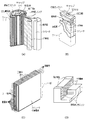
- FIG. 2 shows an example of a laminated structure of a conventional battery.
- FIG. 2 (A) shows a conventional cylindrical battery structure in which the electrode plate has a roll structure.
- the battery of FIG. 2 (A) is provided so that the positive electrode plate and the negative electrode plate face each other, and is wound with a separator interposed between the positive electrode plate and the negative electrode plate, and accommodated in a battery can and sealed. .
- FIG. 2 (B) and 2 (C) are examples of a conventional prismatic battery structure.
- the battery of FIG. 2 (B) is accommodated in a battery can by bending it into a square shape by interposing a separator between the opposing positive electrode plate and negative electrode plate, or by pressing and flattening after winding. Seal.
- the battery of FIG. 2C is obtained by alternately inserting a positive electrode plate and a negative electrode plate into a valley groove of a separator continuous body bent in a zigzag, and pressing it in a zigzag direction to make it flat ( Patent Document 1).
- FIG. 2D shows the structure of a multilayer ceramic capacitor, although it is not a battery structure.
- the multilayer ceramic capacitor shown in FIG. 2D has a structure in which dielectric ceramics and internal electrodes are alternately stacked in a comb shape.
- 2A to 2C are applied not only to alkaline storage batteries such as nickel hydride secondary batteries but also to lithium ion secondary batteries.
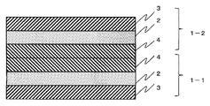
- FIG. 3A is a perspective view illustrating a configuration of a solid-state secondary battery
- FIG. 3B is a cross-sectional view illustrating a cross-section of the solid-state secondary battery.
- the secondary battery 1 shown in FIGS. 3A and 3B has a solid charge layer 2 between the first electrode layer 3 and the second electrode layer 4, so that the secondary battery 1 can be downsized. Expected to be the next battery.
- FIG. 4 shows a stacked structure in which the solid-state secondary batteries of FIG. 3B are connected in series
- FIG. 6 shows a stacked structure in which the single-layered solid-state secondary batteries shown in FIG. 5 are connected in parallel. is there. 4 and 6 each have a six-layer structure.
- the secondary battery having the parallel connection stacked structure needs to provide the insulating layer 9 between the negative electrode terminal 7 and the positive electrode terminal 6 in order to prevent a short circuit. Become. For this reason, the volume increases by the amount of the insulating layer 9, and thus the volume of the secondary battery having the stacked structure connected in parallel becomes larger than that of the stacked structure connected in series.
- the first aspect of the present invention includes two battery parts having a charging layer between the first electrode layer and the second electrode layer, and includes one battery part and the other battery part.
- the first electrode layers, or the second electrode layers of one battery part and the other battery part are adjacently connected, and the second electrode layers of one battery part and the other battery part or one battery part.
- the 1st electrode layer of the other battery part is wiring-connected, and it is a secondary battery characterized by connecting two battery parts in parallel.
- the second aspect of the present invention includes one or a plurality of first battery groups in which a plurality of battery parts configured in the order of a first electrode layer, a charge layer, and a second electrode layer are connected in series, a second electrode layer, a charge 1 and a plurality of second battery groups in which a plurality of battery parts configured in the order of layers and first electrode layers are connected in series, the first electrode layer and the second battery group at the bottom of the first battery group
- the first electrode layers of the uppermost layers of the first battery group, or the uppermost second electrode layer of the first battery group and the second electrode layer of the lowermost layer of the second battery group are adjacently connected, and the uppermost layer of the first battery group
- the second electrode layer and the lowermost second electrode layer of the second battery group, or the lowermost layer first electrode layer of the first battery group and the uppermost first electrode layer of the second battery group are connected by wiring.
- the secondary battery is characterized in that the first battery group and the second battery group are connected in parallel.
- the third aspect of the present invention includes a first electrode layer, a charge layer, and a second electrode layer, in which a plurality of annular battery parts are arranged concentrically, and the first electrode layer of the battery part on the inside or In the secondary battery, the second electrode layer and the first electrode layer or the second electrode layer of the battery part on the outside are adjacently connected, and a plurality of battery parts are connected in parallel.
- a secondary battery having a laminated structure can be formed without providing an insulating layer as in the prior art, the current capacity per unit volume can be improved.
- FIG. 16 is a cross-sectional view showing a direct alternating laminated structure in which the single layers of FIG. 15 are alternately laminated (No. 1).
- FIG. 16 is a cross-sectional view showing a direct alternating laminated structure in which the single layers of FIG. 15 are alternately laminated (No. 2).
- Each embodiment described below is a secondary battery having a stacked structure in which a plurality of thin-film secondary batteries (also referred to as battery units) are stacked in parallel connection as described below. .
- a battery having a charging layer for storing at least electrons between the first electrode layer and the second electrode layer can be widely applied.
- the secondary battery serving as the battery portion an all-solid lithium secondary battery having an inorganic solid electrolyte between the positive electrode and the negative electrode, a solid secondary battery illustrated in FIG. 3, or the like can be used. In this embodiment, the case where the latter solid-state secondary battery is used is illustrated.
- a single layer refers to a structural unit for constituting a secondary battery having a laminated structure.
- FIG. 1 is an explanatory diagram showing the structure of a secondary battery that is a battery unit.
- the secondary battery 1 has a charging layer 2 sandwiched between a first electrode layer 3 and a second electrode layer 4 and is a solid type in which each layer is thinned. Since each layer is thinned, the secondary battery 1 has a sheet shape.
- the first electrode layer 3 is a negative electrode layer
- the second electrode layer 4 is a positive electrode layer.
- the secondary battery 1 is attached on the base material 5, and the negative electrode terminal 6 and the positive electrode terminal 7 are attached to the first electrode layer 3 and the second electrode layer 4, respectively. .
- the secondary battery 1 shows a state in which the secondary battery 1 is mounted on the base material 5, but the base material 5 does not contribute to the operation principle of the secondary battery 1. That is, in the secondary battery 1, the charging layer 2 is sandwiched between the first electrode layer 3 and the second electrode layer 4, and the negative electrode terminal 6 and the positive electrode terminal 7 are attached to the first electrode layer 3 and the second electrode layer 4. It only has to be done.
- the secondary battery 1 illustrated in FIG. 1 is a quantum battery that can be repeatedly charged and discharged using a photoexcitation structure change.
- a quantum battery refers to a battery based on an operation principle that captures electrons by forming a new energy level in a band gap by utilizing a photoexcitation structure change of a metal oxide.
- the charge layer 2 is a layer that stores electrons in a charge operation, releases stored electrons in a discharge operation, and holds (stores) electrons in a state where no charge / discharge is performed. Is formed.
- the photoexcitation structural change is described in, for example, International Publication WO / 2008/053561 and is a phenomenon (technique) discovered by Mr. Akira Nakazawa (also the inventor of the present application) who is the inventor of the application. .
- Akira Nakazawa said that when a semiconductor oxide with a band gap of a predetermined value or more and a translucent metal oxide is provided with an effective excitation energy in an insulating coating state, no electrons are present in the band gap. It was found that many energy levels occur. A quantum battery is charged by capturing electrons at these energy levels, and discharged by releasing the captured electrons.
- the second electrode layer 4 includes an electrode body layer 4A and a p-type metal oxide semiconductor layer 4B formed so as to be in contact with the charging layer 2.
- the p-type metal oxide semiconductor layer 4B is provided to prevent injection of electrons from the electrode main body layer 4A to the charging layer 2.
- the electrode body layer 4A of the first electrode layer 3 and the second electrode layer 4 only needs to be formed as a conductive layer.
- n-type metal oxide semiconductor fine particles covered with an insulating film are attached to the first electrode layer 3 in a thin film shape, and the n-type metal oxide semiconductor undergoes a photoexcitation structure change by ultraviolet irradiation. , Changed to be able to store electrons.
- the secondary battery described below uses a plurality of batteries that function as a single quantum battery shown in FIG.
- the shape of the secondary battery is exemplified as a rectangle, but is not limited to a rectangle, and may be other shapes such as a circle, an ellipse, and a hexagon.
- the film thickness of the first electrode layer 3 and the second electrode layer 4 of the quantum battery shown in FIG. 1 can be about 10 nm to 1 ⁇ m, and the film thickness of the charging layer 2 can be about 50 nm to 10 ⁇ m.
- the quantum battery has a completely solid charge layer. Therefore, unlike the case of the secondary battery in which the charge layer is made of a liquid electrolyte, the quantum battery does not require a sealed structure for enclosing the liquid electrolyte. Moreover, unlike the all-solid-state lithium secondary battery that has been reported recently, no granular electrolyte is used. Therefore, when a quantum battery is applied as a secondary battery, it is easy to create a film structure, and the battery can be configured with only a layer structure. As a result, it is advantageous over the conventional secondary battery in that it can be processed into a relatively free shape.
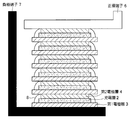
- FIG. 7 shows the parallel connection in which the second electrode layers 4 of the two secondary batteries 1 face each other and are adjacently connected. It is sectional drawing which shows these laminated structures.
- FIG. 8 is a cross-sectional view showing an alternately laminated structure in which the structure shown in FIG. 7 is a single layer and a plurality of single layers are used in parallel connection.
- a single layer 10A shown in FIG. 7 has a laminated structure in which two secondary batteries 1 are connected in parallel. As shown in FIG. 7, one of the two secondary batteries 1 is sandwiched between the negative electrode terminal 7-1 and the positive electrode terminal 6, and the other secondary battery 1 is a positive electrode. The structure is sandwiched between the terminal 6 and the negative terminal 7-2.
- one secondary battery 1 and the other secondary battery 1 are connected to the positive electrode terminal 6 so that the respective second electrode layers 4 face each other. That is, in FIG. 7, one secondary battery 1 is in the order of the first electrode layer 3, the charge layer 2, and the second electrode layer 4 from the negative electrode terminal 7-1 to the positive electrode terminal 6, and the other In the secondary battery 1, the second electrode layer 4, the charging layer 2, and the first electrode layer 3 are arranged in this order from the positive electrode terminal 6 to the negative electrode terminal 7-2.
- the first electrode layer 3 of each of the secondary battery 1 and the other secondary battery 1 is connected to the negative terminals 7-1 and 7-2 by wiring.
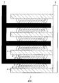
- FIG. 8 is a structure in which three single layers 10A shown in FIG. 7 are laminated.
- the negative electrode terminal 7-1 of another single layer 10A is laminated on the negative electrode terminal 7-2 of the single layer 10A.
- two negative terminals 7-1 and 7- between the laminated single layers 10A are used. 2 is one negative terminal 7.
- FIG. 8 illustrates the case where the negative electrode terminal 7 is connected over the entire surface of the first electrode layer 3.
- the negative electrode terminal 7 may be connected to the first electrode layer 3 as long as electrons can be exchanged. You may make it connect with at least one part.
- the positive electrode terminal 6 may be connected to at least a part of the second electrode layer 4 for the same reason.
- FIG. 8 illustrates the case where three single layers 10A are stacked, two or four or more single layers 10A may be stacked.
- FIG. 9 shows the second electrode layers 4 of the two secondary batteries 1.
- FIG. 2 is a cross-sectional view showing a stacked structure of parallel connection by connecting adjacently facing each other.
- FIG. 10 is a cross-sectional view showing an alternately laminated structure in which the structure shown in FIG. 9 is a single layer and a plurality of single layers are used in parallel connection.
- a single layer 20A shown in FIG. 9 has a configuration in which the first electrode layer 3 also serves as the lead-out negative terminals 7-1 and 7-3 shown in FIG. That is, in FIG. 9, the two secondary batteries 1 have a structure in which the two secondary batteries 1 sandwich the positive electrode terminal 6 with the second electrode layer 4 facing each other.
- the first electrode layer 3-1 of one secondary battery 1 corresponds to the lead-out negative electrode terminal 7-1 of FIG. 7, and the first electrode layer 3-2 of the other secondary battery 1 is formed of FIG. It corresponds to the negative terminal 7-2.
- the volume of the single layer 20A in FIG. 9 is smaller than that of the single layer 10A in FIG. 7 by the amount of the negative electrode terminals 7-1 and 7-2 for extraction.
- 10 is a structure in which three single layers 20A are stacked.
- the first electrode layer 3-1 of another single layer 20A is stacked on the first electrode layer 3-2 of the single layer 20A.
- the first electrode layer 3 corresponds to the lead-out negative electrode terminal 7. Therefore, in the stacked layer 20 ⁇ / b> B of FIG. 10, the first electrode layer 3 extends in one direction so that the first electrode layer 3 is connected to the negative electrode terminal 7 by wiring.
- the insulator provided between the negative electrode terminal and the positive electrode terminal becomes unnecessary, as in the structure of FIGS.
- the current can be further reduced by the amount corresponding to the negative terminals 7-1 and 7-2, and the current capacity per unit volume is also improved.
- FIG. 11 shows the parallel connection by connecting the first electrode layers 3 of two secondary batteries 1 face to face adjacent to each other. It is sectional drawing which shows a laminated structure.
- FIG. 12 is a cross-sectional view showing an alternately laminated structure in which the structure shown in FIG. 11 is a single layer and a plurality of single layers are used in parallel connection.
- one secondary battery 1 is sandwiched between the positive electrode terminal 6-1 and the negative electrode terminal 7, and the other secondary battery 1 is interposed between the negative electrode terminal 7 and the positive electrode terminal 6-2.
- the structure is sandwiched between.
- the single layer 30A has a structure in which the negative electrode terminal 7 is sandwiched so that the first electrode layers 3 of one secondary battery 1 and the other secondary battery 1 face each other.
- the first electrode layer 3 of one secondary battery 1 and the first electrode layer 3 of the other secondary battery 1 are adjacently connected, and the second electrode layer 4 of the one secondary battery 1 and the other secondary battery 1 are connected to each other.
- the second electrode layer 4 of the battery 1 is connected to the positive terminals 6-1 and 6-2 by wiring.
- the single layer 30A is sandwiched between the positive electrode terminal 6-1 and the negative electrode terminal 7, and the secondary battery 1 is connected to the second terminal 1 from the positive electrode terminal 6-1 toward the negative electrode terminal 7.
- the electrode layer 4, the charge layer 2, and the first electrode layer 3 are arranged in this order.
- the other secondary battery 1 sandwiched between the negative electrode terminal 7 and the positive electrode terminal 6-2 has the first electrode layer 3, the charge layer 2, the second electrode 2 from the negative electrode terminal 7 toward the positive electrode terminal 6-2.
- the electrode layers 4 are arranged in this order.
- 12 is a structure in which three single layers 30A are stacked.
- the positive terminal 6-1 of another single layer 30A is stacked on the positive terminal 6-2 of the single layer 30A.
- two positive terminals 6-1 and 6- 2 is one positive terminal 6.
- FIGS. 11 and 12 Since the structure shown in FIGS. 11 and 12 eliminates the need to provide an insulator between the negative electrode terminal and the positive electrode terminal when connected in parallel as in the structures of FIGS. The volume is reduced and the current capacity per unit volume is improved.
- FIG. 13 shows the first electrode layer 3 of the two secondary batteries 1
- FIG. 2 is a cross-sectional view showing a stacked structure of parallel connection by connecting adjacently facing each other.
- FIG. 14 is a cross-sectional view showing an alternately stacked structure in which the structure shown in FIG. 13 is a single layer and a plurality of single layers are used in parallel connection.
- a single layer 40A shown in FIG. 13 has a configuration in which the second electrode layer 4 also serves as the lead-out positive terminals 6-1 and 6-2 shown in FIG. That is, in FIG. 13, the two secondary batteries 1 have a structure in which the two secondary batteries 1 sandwich the negative electrode terminal 7 so that the first electrode layers 3 face each other.
- the second electrode layer 4-1 of one secondary battery 1 corresponds to the lead-out positive electrode terminal 6-1 shown in FIG. 11, and the second electrode layer 4-2 of the other secondary battery 1 is shown in FIG. It corresponds to the positive terminal 6-2.
- the single layer 40A in FIG. 13 has a smaller volume than the single layer 30A in FIG. 11 by the amount of the positive electrode terminals 6-1 and 6-2 for lead-out.
- 14 is a structure in which three single layers 40A are stacked.
- the second electrode layer 4-1 of the other single layer 40A is stacked on the second electrode layer 4-2 of the single layer 40A.
- the second electrode layer 4 corresponds to a lead-out positive electrode terminal 6. Therefore, in the stacked layer 40 ⁇ / b> B of FIG. 14, the second electrode layer 4 extends in one direction so that the second electrode layer 4 is connected to the positive electrode terminal 6 by wiring.
- FIGS. 13 and 14 eliminates the need for an insulator provided between the negative electrode terminal and the positive electrode terminal, and further reduces the size of the positive electrode terminal 6 to be laminated.
- the current capacity per unit volume is also improved.
- the parallel stack structure shown in FIG. 14 reduces the manufacturing burden for forming the parallel-connected stack 40B. That is, the stacked layer 40B of FIG. 14 may be manufactured by making the secondary battery 1 so that the second electrode layer 4 extends in one direction, and the second electrode extended when the single layer 40A is stacked. It can be completed simply by connecting the layer 4 to the positive terminal 6.
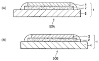
- FIG. 15 is a cross-sectional view showing a single layer structure forming the direct alternating layer structure.
- FIG. 15 shows two types of single-layer structures.
- a single layer 50 ⁇ / b> A shown in FIG. 15A has a structure in which the charging layer 2 and the second electrode layer 4 are formed on the extended first electrode layer 3.
- a single layer 50 ⁇ / b> B illustrated in FIG. 15B has a structure in which the charging layer 2 and the first electrode layer 3 are formed on the extended second electrode layer 4.
- FIGS. 15A and 15B two types of single layer 50A and single layer 50B shown in FIGS. 15A and 15B are alternately and directly stacked to form a parallel connection stacked structure.
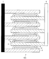
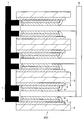
- FIGS. 16 and 17 are cross-sectional views showing a direct alternating laminated structure in which two types of single layers 50A and 50B shown in FIG. 15 are alternately laminated.
- the stacking shown in FIGS. 16 and 17 is different in the stacking order of the single layer 50A and the single layer 50B.
- 16 has a structure in which a total of six layers are laminated in the order of a single layer 50A, a single layer 50B, a single layer A, a single layer B,... From the bottom.
- the first electrode layer 3 of the single layer 50 ⁇ / b> A extends in one direction so that it can be connected to the negative electrode terminal 7. That is, a negative electrode terminal for lead-out is unnecessary.
- the second electrode layer 4 of the single layer 50B is also extended in one direction, it can be connected to the positive electrode terminal 6, and a positive electrode terminal for lead-out is unnecessary.
- 17 has a structure in which a total of six layers are laminated in the order of a single layer 50B, a single layer 50A, a single layer 50B, a single layer 50A,... Also in this case, since the first electrode layer 3 of the single layer 50A and the second electrode layer 4 of the single layer 50B are extended in one direction and connected to the negative electrode terminal 7 and the positive electrode terminal 6, the lead-out terminal is This is unnecessary, and the total capacity of the battery having the laminated structure is reduced accordingly.
- a plurality of charging layers 2 between the first electrode layer 3 and the second electrode layer 4 are provided.
- the secondary battery 1 is used to connect adjacently so that the first electrode layer 3 or the second electrode layer 4 of each secondary battery 1 faces each other, and the second electrode layer 4 or the first electrode layer 3 is wired.
- the manufacturing process of the secondary battery having a laminated structure it is conceivable to form a laminated structure by laminating the sheet-like secondary battery 1 cut into a predetermined size. Therefore, a laminated structure having the same area can be formed. Furthermore, even when a defective portion is generated in the sheet-like secondary battery 1, a stacked structure having the same area can be formed while avoiding the defective portion.
- the laminated structure in which the secondary battery 1 is formed using the negative electrode terminal 7, the positive electrode terminal 6, the first electrode layer 3, and the second electrode layer 4 as a base material and these are formed as a single layer has been described.
- 2nd Embodiment demonstrates the parallel laminated structure using what attached the secondary battery 1 to the base material 5 as shown in FIG.
- FIG. It is sectional drawing which shows a layer structure.
- a single layer 60A shown in FIG. 18 includes, for example, a secondary battery 1 in which a base (support) 5 made of an insulator such as polyimide is arranged in the order of a first electrode layer 3, a charge layer 2, and a second electrode layer 4. And the positive electrode terminal 6 is connected to the second electrode layer 4.
- a base (support) 5 made of an insulator such as polyimide is arranged in the order of a first electrode layer 3, a charge layer 2, and a second electrode layer 4.
- the positive electrode terminal 6 is connected to the second electrode layer 4.
- the 1st electrode layer 3 is attached to the base material 5, in order to connect the negative electrode terminal 7 to the 1st electrode layer 3, the 1st electrode layer 3 is unidirectionally attached with the attached base material 5
- the negative electrode terminal 7 is connected to the extended portion from the inside by wiring. That is, in FIG. 18, the negative electrode terminal 7 is connected to the upper surface portion of the extended first electrode layer 3.
- FIG. 18 illustrates the case where the positive electrode terminal 6 is connected over the entire surface of the second electrode layer 4, but the positive electrode terminal 6 may be connected to a part of the second electrode layer 4. Good.
- FIG. 19 is a cross-sectional view showing a laminated structure in which two secondary batteries 1 attached to a base material 5 are connected in parallel.
- the 19 has a structure in which the positive electrode terminal 6 is sandwiched so that the second electrode layers 4 of the secondary battery 1 attached to the substrate 5 face each other.
- the positive electrode terminal 6 is connected to each second electrode layer 4 and can exchange electrons.
- the negative electrode terminal 7 is connected to the extended first electrode layer 3 as described above, and can exchange electrons.
- FIG. 20 is a cross-sectional view showing a laminated structure of parallel connection using a plurality of single layers 60B shown in FIG.
- the stacked 60C in parallel connection shown in FIG. 20 has a structure in which three single layers 60B are stacked.
- FIG. 21 shows a single layer structure of alternating layering of the parallel connection when the secondary battery is attached to the base material It is sectional drawing.
- a single layer 70A shown in FIG. 21 includes, for example, a secondary battery 1 including a base material (support) 5 made of an insulator such as polyimide in the order of the second electrode layer 4, the charge layer 2, and the first electrode layer 3. And the negative electrode terminal 7 is connected to the second electrode layer 4.
- the second electrode layer 4 is attached to the base material 5, in order to connect the positive electrode terminal 6 to the second electrode layer 4, the second electrode layer 4 is extended in one direction together with the attached base material.
- the positive electrode terminal 6 is connected to the extended portion by wiring from the inside. That is, in FIG. 21, the positive electrode terminal 6 is connected to the upper surface portion of the extended second electrode layer 4.
- FIG. 21 illustrates the case where the negative electrode terminal 7 is connected over the entire surface of the first electrode layer 3. However, the negative electrode terminal 7 may be connected to a part of the first electrode layer 3. Good.
- FIG. 22 is a cross-sectional view showing a laminated structure in which two secondary batteries 1 attached to the base material 5 are connected in parallel.
- the 22 has a structure in which the negative electrode terminal 7 is sandwiched so that the first electrode layers 3 of the two secondary batteries 1 face each other.
- the negative terminal 7 is connected to each second electrode layer 4 and can exchange electrons.
- the positive electrode terminal 6 is connected to the extended second electrode layer 4 and can exchange electrons.
- FIG. 23 is a cross-sectional view showing a parallel stacked structure using a plurality of single layers 70B shown in FIG. A stacked 70C in parallel connection shown in FIG. 23 has a structure in which three single layers 70B are stacked.
- 3rd Embodiment is a laminated structure which combined the laminated structure by series connection, and the laminated structure by parallel connection.
- FIG. 24 shows a combination of a stacked structure of serial connection and a stacked structure of parallel connection using the two types of single layers 50A and 50B illustrated in FIG. It is sectional drawing which shows a structure.
- FIG. 24 exemplifies a stacked structure in which three series connections and two parallel connections are combined. That is, in FIG. 24, a three-layer series connection stack using the single layer 50A illustrated in FIG. 15A and a three-layer series connection stack using the single layer 50B illustrated in FIG. Are connected in parallel. Two parallel connections are formed.
- the stacked structure in which the single layers 50A in FIG. 15A are connected in series is also referred to as a first battery group, and the stacked structure in which the single layers 50B in FIG. 15B are connected in series is also referred to as a second battery group.
- the voltage of the secondary battery 1 is V 0 and the current capacity of the single layer is I 0
- the lead electrode to the first electrode layer 3 and the second electrode layer 4 extends the first electrode layer 3 and the second electrode layer 4, and the negative electrode terminal 7 and the positive electrode terminal 6 are stacked.
- the negative electrode terminal 7 and the positive electrode terminal 6 are connected to the first electrode layer 3 and the second electrode layer 4 so as to exchange electrons.
- the stack 80A illustrated in FIG. 24 is an example of a combination structure of series connection and parallel connection.
- the number of stacked layers of the single layer 50A and the single layer 50B connected in series is three, but is not limited to this.
- the number of stacked layers connected in parallel is two, it is not limited to this.
- FIG. 24 illustrates a case where a single-layer 50B is connected in series to a single-layer 50A in series connection, but conversely, a single-layer 50B is connected in series to a single-layer 50B in series connection. It may be the case where a connection is placed.
- FIG. 25 is a view showing a laminated structure formed by annularly forming the single layers 50A and 50B shown in FIG. 15 and arranging the single layers 50A and 50B alternately concentrically. is there.
- the single layer 50A is wound in an annular shape on the innermost side
- the single layer 50B is wound in an annular shape on the outer side
- the single layer 50A is wound in an annular shape on the outer side of the single layer 50B.
- the single layer 50A and the single layer 50B are wound alternately.
- the innermost single layer 50A is wound so that the second electrode layer 4 is on the inner side.
- the innermost single layer 50A may be wound around the rod-like positive electrode terminal, or if the second electrode layer 4 of the single layer 50A can be wire-connected to the positive electrode terminal, there is no rod-like positive electrode terminal. Also good.
- the innermost single layer may be the single layer 50B, and the first electrode layer 3 may be wound inside.
- the single layer 50B may be wound around the rod-like negative electrode terminal so that the inner first electrode layer 3 can be connected by wire, or the wire connection can be made without the rod-like negative electrode terminal.
- the single layer 50B wound outside the innermost single layer 50A is wound outside the inner single layer 50A so that its own first electrode layer 3 faces the first electrode layer 3 of the inner single layer 50A. It is burned.
- the first electrode layer 3 of the single layer 50B and the inner single layer 50A is connected to the negative electrode terminal via a lead wire.
- the single layer 50A wound outside the single layer 50B is wound so that the second electrode layer 4 of the single layer 50A faces the second electrode layer 4 of the inner single layer 50B. Further, the second electrode layer of the single layer 50A and the inner single layer 50B is connected to the positive electrode terminal through a lead wire.
- the first electrode layer 3 or the second electrode layer 4 of the inner single layer 50A or the single layer 50B and the outer single faces each other and is formed in parallel connection.
- the stacked layer 90A shown in FIG. 25 is exemplified by a layered structure in which the cross section of the stacked structure is stacked concentrically, the cross section of the stacked structure may be elliptical or flat.
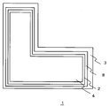
- the fifth embodiment is characterized by the shape of the battery parts to be stacked while improving the current capacity per unit volume as in the first to fourth embodiments.
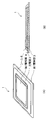
- FIG. 26 is an explanatory diagram showing the secondary battery 1 according to the fifth embodiment.
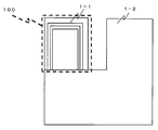
- FIG. 26 is a view of the secondary battery 1 having the structure illustrated in FIG. 1 as viewed from above, and the secondary battery 1 of the fifth embodiment has an L shape.
- FIG. 27 is an explanatory view illustrating the structure when the secondary batteries of FIG. 26 are connected in series.
- FIG. 28 is a cross-sectional view of a stacked structure of secondary batteries connected in series.
- FIG. 27 exemplifies a case where two secondary batteries 1-1 and secondary battery 1-2 are connected in series for the sake of simplicity, but the number of stacked layers is not particularly limited.
- both the secondary batteries 1-1 and 1-2 are in order of the first electrode layer 3, the charging layer 2, and the second electrode layer 4 from the bottom. .
- the sheet-like secondary battery 1-2 is rotated 90 degrees counterclockwise on the same plane and stacked on the secondary battery 1-1. Then, a non-overlapping portion is exposed in the relationship between the secondary battery 1-1 below the stack and the secondary battery 1-2 above the stack.
- This non-overlapping portion can be a lead-out portion 100 that extracts electrons from the first electrode layer 3 or the second electrode layer 4.
- FIG. 29 is an explanatory diagram illustrating a structure when the secondary batteries of FIG. 26 are connected in parallel.
- FIG. 29 also illustrates a case where two secondary batteries 1-1 and 1-2 are connected in parallel, but the number of stacked layers is not particularly limited.
- FIG. 30 is a cross-sectional view of a stacked structure of secondary batteries connected in parallel.
- the secondary battery 1-1 has the first electrode layer 3,
- the charging layer 2 and the second electrode layer 4 are in this order, and the secondary battery 1-2 is in the order of the second electrode layer 4, the charging layer 2, and the first electrode layer 3 from the bottom.
- This non-overlapping portion can be a lead-out portion 100 that extracts electrons from the first electrode layer 3 or the second electrode layer 4.
- the electrons are extracted from the first electrode layer 3 or the second electrode layer 4.
- the part 100 is formed inside the outer shape of the laminated structure.
- the structure described in the first to fourth embodiments can be applied to the laminated structure of the secondary battery.
- the lead-out portion 100 for taking out electrons from the first electrode layer 3 or the second electrode layer 4 is secured while improving the current capacity of the entire secondary battery having the stacked structure. can do.
- a stacked structure in which a stacked structure in series connection and a stacked structure in parallel connection are combined can be used.
- the shape of the secondary battery 1 is not limited to the L shape. That is, when a plurality of secondary batteries 1 are stacked, a non-overlapping portion is formed inside the outer shape of the stacked structure between the secondary battery 1 above the stack and the secondary battery below the stack. Any shape can be used as long as it can be generated.
- the secondary battery may be a triangle such as a right triangle, a T shape, a U shape, or the like.
- FIG. 8 shows the case where the negative electrode terminal and the positive electrode terminal are provided on the left and right, but the negative electrode terminal and the positive electrode terminal may be provided on the front side and the back side in the normal direction of the paper surface. May be provided on the left side of the paper surface and the positive electrode terminal may be provided in front of the normal direction of the paper surface.
- the negative electrode terminal and the positive electrode terminal may be plate-shaped or rod-shaped, and are not limited to one member, and a plurality of members may be in the normal direction of the paper surface. It may be arranged.
- a case where a plurality of single-layer batteries are arranged (stacked) side by side is shown, but a plurality of single-layer batteries may be provided side by side.
- the extraction electrode for transferring electrons to the first electrode layer and / or the second electrode layer is the entire surface of the first electrode layer and / or the second electrode layer. However, it may be connected to a part of the first electrode layer and / or the second electrode layer.
- the single layer formation process is not particularly limited, and various methods can be applied.
- the secondary battery has been described assuming a solid-state secondary battery.
- the charge layer between the first electrode layer and the second electrode layer may be an organic solid material or an inorganic solid material.
- the secondary battery is exemplified as a plane, but the secondary battery is not limited to a plane.
- the laminated structure described in the first to third embodiments described above may be formed using a secondary battery having a curvature such that the cross section is an arc.
Abstract
Description
以下では、本発明の二次電池の第1の実施形態及び変形実施形態について、図面を参照しながら詳細に説明する。
図1は、電池部である二次電池の構造を示す説明図である。図1に示すように、二次電池1は、第1電極層3と第2電極層4との間に挟まれた充電層2を有し、各層を薄膜化した固体型のものである。各層が薄膜化されているので、二次電池1はシート状からなっている。図1では、第1電極層3は負電極の層であり、第2電極層4は正電極の層であるものとする。
次に、図1の電池部である二次電池1を複数個用いて並列接続させた積層構造を、図面を参照しながら説明する。
図7は、2個の二次電池1の第2電極層4を向かい合わせにして隣接接続させて並列接続の積層構造を示す断面図である。
図9は、2個の二次電池1の第2電極層4を向かい合わせに隣接接続させて並列接続の積層構造を示す断面図である。
図11は、2個の二次電池1の第1電極層3を向かい合わせに隣接接続させて並列接続の積層構造を示す断面図である。
図13は、2個の二次電池1の第1電極層3を向かい合わせに隣接接続させて並列接続の積層構造を示す断面図である。
図15は、直接交互積層構造を形成する単層構造を示す断面図である。図15では、2種類の単層構造を示す。図15(A)に示す単層50Aは、延設した第1電極層3に充電層2及び第2電極層4が形成された構造である。図15(B)に示す単層50Bは、延設した第2電極層4に充電層2及び第1電極層3が形成された構造である。
以上のように、上述した各実施形態によれば、第1電極層3及び第2電極層4の間に充電層2を有する複数の二次電池1を用いて、各二次電池1の第1電極層3又は第2電極層4がお互いに向かい合うようにして隣接接続し、第2電極層4又は第1電極層3を配線接続して、並列接続とすることで、従来必要だった絶縁層が不要となるので、その分、電池の全容量が小さくなり、単位容積当たりの電流容量が向上する。
次に、本発明の二次電池の第2の実施形態を、図面を参照しながら説明する。
図18は、二次電池1が基材5に取り付けられた場合の並列接続の交互積層の単層構造を示す断面図である。
図21は、二次電池が基材に取り付けられた場合の並列接続の交互積層の単層構造を示す断面図である。図21に示す単層70Aは、例えば、ポリイミド等の絶縁体からなる基材(支持体)5に、第2電極層4、充電層2及び第1電極層3の順序でなる二次電池1を取り付け、第2電極層4に負極端子7を接続させた構造である。
次に、本発明の二次電池の第3の実施形態について図面を参照しながら説明する。
図24は、図15に例示した2種類の単層50A及び50Bを用いて、直列接続の積層構造と並列接続の積層構造とを組み合わせた積層構造を示す断面図である。
図25は、図15に示す単層50A及び50Bを環状にし、単層50Aと単層50Bとが交互に同心円状に配置させて形成した積層構造を示す図である。
次に、本発明の二次電池の第5の実施形態を、図面を参照しながら詳細に説明する。
(F-1)第1~第5の実施形態で説明した積層構造の二次電池の積層数は、特に限定されるものではない。上述したように、積層数が多くなると、積層構造の二次電池の電流容量I1(I1=N × I0)は大きくなるが、その分、積層構造の二次電池の容量も大きくなる。従って、二次電池の使用される用途や利用態様等に応じて、積層数を適宜決定することができる。
Claims (10)
- 第1電極層と第2電極層との間に充電層を有する2個の電池部を備え、
一方の上記電池部及び他方の上記電池部の上記第1電極層同士、又は、一方の上記電池部及び他方の上記電池部の上記第2電極層同士を隣接接続させ、
一方の上記電池部及び他方の上記電池部の上記第2電極層同士、又は、一方の上記電池部及び他方の上記電池部の上記第1電極層同士を配線接続させ、
上記2個の電池部を並列接続させたことを特徴とする二次電池。 - 一方の上記電池部が、第1電極端子と第2電極端子との間に配置され、
他方の上記電池部が、一方の上記電池部と接続する上記第2電極端子と、他の第1電極端子との間に配置される
ことを特徴とする請求項1に記載の二次電池。 - 請求項2に記載の二次電池を1つの構成単位である構成単位電池とし、複数の構成単位電池を並列接続させる二次電池であって、
ある構成単位電池の第1電極端子と、この構成単位電池に隣接する別の構成単位電池の第1電極端子とを1個の第1電極端子に置き換えることを特徴とする二次電池。 - 一方の上記電池部が、第2電極端子と第1電極端子との間に配置され、
他方の上記電池部が、一方の上記電池部と接続する上記第1電極端子と、他の第2電極端子との間に配置される
ことを特徴とする請求項1に記載の二次電池。 - 請求項4に記載の二次電池を1つの構成単位である構成単位電池とし、複数の構成単位電池を並列接続させる二次電池であって、
ある構成単位電池の第2電極端子と、この構成単位電池に隣接する別の構成単位電池の第2電極端子とを1個の第2電極端子に置き換えることを特徴とする二次電池。 - 請求項1に記載の二次電池を1つの構成単位である構成単位電池とし、複数の構成単位電池を並列接続させることを特徴とする二次電池。
- 第1電極層、充電層、第2電極層の順序で構成される複数の電池部を直列接続させた1又は複数の第1電池群と、
第2電極層、充電層、第1電極層の順序で構成される複数の電池部を直列接続させた1又は複数の第2電池群と
を備え、
上記第1電池群の最下層の第1電極層と上記第2電池群の最上層の第1電極層同士、又は、上記第1電池群の最上層第2電極層と上記第2電池群の最下層の第2電極層同士を隣接接続させ、
上記第1電池群の最上層の第2電極層と上記第2電池群の最下層の第2電極層同士、又は、上記第1電池群の最下層第1電極層と上記第2電池群の最上層の第1電極層同士を配線接続させ、
上記第1電池群と上記第2電池群とを並列接続させたことを特徴とする二次電池。 - 上記第1電極層及び又は上記第2電極層が延設されたものであり、延設された上記第1電極層及び又は上記第2電極層が、第1電極端子及び又は第2電極端子に接続するものである請求項1、6又は7のいずれかに記載の二次電池。
- 第1電極層、充電層、第2電極層の順序で構成され、環状にした複数の電池部を同心円状に配置させ、
内側にある電池部の第1電極層又は第2電極層と、外側にある電池部の第1電極層又は第2電極層とが隣接接続し、複数の電池部を並列接続させた二次電池。 - 上記電池部の形状が隣接する他の電池部との間で重複しない部分を有する形状であって、その重複しない部分が配線接続される部分であることを特徴とする請求項1~8のいずれかに記載の二次電池。
Priority Applications (8)
| Application Number | Priority Date | Filing Date | Title |
|---|---|---|---|
| US14/388,414 US10347893B2 (en) | 2012-04-09 | 2013-04-05 | Secondary battery |
| JP2014510148A JP6184941B2 (ja) | 2012-04-09 | 2013-04-05 | 二次電池 |
| CA2867651A CA2867651C (en) | 2012-04-09 | 2013-04-05 | Secondary battery |
| EP13774976.8A EP2838148A4 (en) | 2012-04-09 | 2013-04-05 | RECHARGEABLE BATTERY |
| CN201380019149.8A CN104221200B (zh) | 2012-04-09 | 2013-04-05 | 二次电池 |
| KR1020147021653A KR101616883B1 (ko) | 2012-04-09 | 2013-04-05 | 이차전지 |
| TW102112491A TWI504038B (zh) | 2012-04-09 | 2013-04-09 | Secondary battery |
| TW103139551A TWI535090B (zh) | 2012-04-09 | 2013-04-09 | Secondary battery |
Applications Claiming Priority (2)
| Application Number | Priority Date | Filing Date | Title |
|---|---|---|---|
| JPPCT/JP2012/059706 | 2012-04-09 | ||
| PCT/JP2012/059706 WO2013153603A1 (ja) | 2012-04-09 | 2012-04-09 | 二次電池 |
Publications (1)
| Publication Number | Publication Date |
|---|---|
| WO2013154046A1 true WO2013154046A1 (ja) | 2013-10-17 |
Family
ID=49327213
Family Applications (2)
| Application Number | Title | Priority Date | Filing Date |
|---|---|---|---|
| PCT/JP2012/059706 WO2013153603A1 (ja) | 2012-04-09 | 2012-04-09 | 二次電池 |
| PCT/JP2013/060467 WO2013154046A1 (ja) | 2012-04-09 | 2013-04-05 | 二次電池 |
Family Applications Before (1)
| Application Number | Title | Priority Date | Filing Date |
|---|---|---|---|
| PCT/JP2012/059706 WO2013153603A1 (ja) | 2012-04-09 | 2012-04-09 | 二次電池 |
Country Status (8)
| Country | Link |
|---|---|
| US (1) | US10347893B2 (ja) |
| EP (1) | EP2838148A4 (ja) |
| JP (1) | JP6184941B2 (ja) |
| KR (1) | KR101616883B1 (ja) |
| CN (1) | CN104221200B (ja) |
| CA (1) | CA2867651C (ja) |
| TW (2) | TWI504038B (ja) |
| WO (2) | WO2013153603A1 (ja) |
Cited By (7)
| Publication number | Priority date | Publication date | Assignee | Title |
|---|---|---|---|---|
| WO2015087388A1 (ja) * | 2013-12-10 | 2015-06-18 | 株式会社日本マイクロニクス | 二次電池及びその製造方法 |
| JP2015115130A (ja) * | 2013-12-10 | 2015-06-22 | 株式会社日本マイクロニクス | 二次電池及びその製造方法 |
| CN105164846A (zh) * | 2014-03-26 | 2015-12-16 | 日本麦可罗尼克斯股份有限公司 | 堆叠型二次电池 |
| CN106463617A (zh) * | 2014-03-18 | 2017-02-22 | 日本麦可罗尼克斯股份有限公司 | 电池 |
| WO2017043011A1 (ja) * | 2015-09-08 | 2017-03-16 | 株式会社日本マイクロニクス | 二次電池、及び二次電池の製造方法 |
| US20190020005A1 (en) * | 2016-01-05 | 2019-01-17 | Kabushiki Kaisha Nihon Micronics | Cell structure unit and multilayer cell |
| JP2019096917A (ja) * | 2019-03-27 | 2019-06-20 | セイコーインスツル株式会社 | コイン型電気二重層キャパシタの積層並列接続体 |
Families Citing this family (9)
| Publication number | Priority date | Publication date | Assignee | Title |
|---|---|---|---|---|
| WO2015105022A1 (ja) * | 2014-01-07 | 2015-07-16 | コニカミノルタ株式会社 | 有機エレクトロルミネセンスデバイス |
| JP6443798B2 (ja) | 2014-03-24 | 2018-12-26 | パナソニックIpマネジメント株式会社 | 蓄電素子及び蓄電素子の製造方法 |
| JP6572015B2 (ja) | 2015-06-25 | 2019-09-04 | 株式会社日本マイクロニクス | 二次電池の製造方法 |
| WO2017002284A1 (ja) * | 2015-07-02 | 2017-01-05 | 株式会社日本マイクロニクス | 電池、及びその充放電方法 |
| CN105742722B (zh) * | 2016-04-27 | 2019-02-01 | 惠州亿纬锂能股份有限公司 | 卷绕式软包弧形电池及卷绕式软包弧形电池制备方法 |
| JP6861029B2 (ja) * | 2016-12-27 | 2021-04-21 | 株式会社日本マイクロニクス | 積層電池 |
| JP6773133B2 (ja) * | 2017-01-13 | 2020-10-21 | 株式会社村田製作所 | 二次電池 |
| JP7437786B2 (ja) * | 2019-07-12 | 2024-02-26 | パナソニックIpマネジメント株式会社 | 電池 |
| CN112397776B (zh) * | 2020-10-27 | 2021-10-19 | 广东东邦科技有限公司 | 一种Ga、Al共掺杂LLZO固态电解质、多元固态电池及其制备方法 |
Citations (7)
| Publication number | Priority date | Publication date | Assignee | Title |
|---|---|---|---|---|
| JP2003257472A (ja) * | 2002-02-28 | 2003-09-12 | Sanyo Electric Co Ltd | インサイドアウト型電池 |
| JP2006066083A (ja) * | 2004-08-24 | 2006-03-09 | Nissan Motor Co Ltd | 組電池 |
| JP2006185662A (ja) * | 2004-12-27 | 2006-07-13 | Matsushita Electric Ind Co Ltd | エネルギーデバイスおよびその製造方法 |
| JP2007012584A (ja) * | 2005-06-01 | 2007-01-18 | Nissan Motor Co Ltd | 組電池およびこれを搭載した車両 |
| WO2008053561A1 (fr) | 2006-11-02 | 2008-05-08 | Shinoda Plasma Co., Ltd. | Élément de étection de champ électrique et dispositif d'affichage utilisant celui-ci |
| JP2009140707A (ja) | 2007-12-05 | 2009-06-25 | Dainippon Printing Co Ltd | 角形電池用極板群の製造方法および装置 |
| WO2012020700A1 (ja) * | 2010-08-09 | 2012-02-16 | 株式会社 村田製作所 | 積層型固体電池 |
Family Cites Families (12)
| Publication number | Priority date | Publication date | Assignee | Title |
|---|---|---|---|---|
| AU7496200A (en) * | 1999-11-23 | 2001-06-04 | Valence Technology (Nevada), Inc. | Multi-layer electrochemical cell devices |
| TW465137B (en) | 2000-01-26 | 2001-11-21 | Ind Tech Res Inst | Stacked battery structure |
| JP2001345095A (ja) * | 2000-06-01 | 2001-12-14 | Nisshinbo Ind Inc | 電極構造体、電池及び電気二重層キャパシタの製造方法 |
| CN1497760A (zh) | 2002-10-10 | 2004-05-19 | 日产自动车株式会社 | 叠层电池、组装电池及车辆 |
| CN1321477C (zh) | 2003-10-28 | 2007-06-13 | 比亚迪股份有限公司 | 锂离子二次电池 |
| JPWO2007026492A1 (ja) | 2005-08-30 | 2009-03-05 | 富士重工業株式会社 | リチウムイオンキャパシタ |
| JP4495751B2 (ja) | 2007-07-24 | 2010-07-07 | 太陽誘電株式会社 | 電気化学デバイスの製造方法 |
| KR101252297B1 (ko) | 2009-08-19 | 2013-04-05 | 한국전자통신연구원 | 진공밀폐형 플렉서블 필름 일차전지 및 그의 제조방법 |
| CN102035040B (zh) * | 2009-09-28 | 2013-05-01 | 清华大学 | 制造组合电池的方法及组合电池 |
| KR101451044B1 (ko) * | 2010-07-26 | 2014-10-15 | 닛산 지도우샤 가부시키가이샤 | 쌍극형 전지 |
| KR101605765B1 (ko) | 2010-10-07 | 2016-03-24 | 구엘라 테크놀로지 가부시키가이샤 | 이차 전지 |
| WO2013161053A1 (ja) | 2012-04-27 | 2013-10-31 | 株式会社日本マイクロニクス | 二次電池 |
-
2012
- 2012-04-09 WO PCT/JP2012/059706 patent/WO2013153603A1/ja active Application Filing
-
2013
- 2013-04-05 CN CN201380019149.8A patent/CN104221200B/zh not_active Expired - Fee Related
- 2013-04-05 CA CA2867651A patent/CA2867651C/en not_active Expired - Fee Related
- 2013-04-05 JP JP2014510148A patent/JP6184941B2/ja not_active Expired - Fee Related
- 2013-04-05 WO PCT/JP2013/060467 patent/WO2013154046A1/ja active Application Filing
- 2013-04-05 EP EP13774976.8A patent/EP2838148A4/en not_active Withdrawn
- 2013-04-05 US US14/388,414 patent/US10347893B2/en not_active Expired - Fee Related
- 2013-04-05 KR KR1020147021653A patent/KR101616883B1/ko active IP Right Grant
- 2013-04-09 TW TW102112491A patent/TWI504038B/zh not_active IP Right Cessation
- 2013-04-09 TW TW103139551A patent/TWI535090B/zh active
Patent Citations (7)
| Publication number | Priority date | Publication date | Assignee | Title |
|---|---|---|---|---|
| JP2003257472A (ja) * | 2002-02-28 | 2003-09-12 | Sanyo Electric Co Ltd | インサイドアウト型電池 |
| JP2006066083A (ja) * | 2004-08-24 | 2006-03-09 | Nissan Motor Co Ltd | 組電池 |
| JP2006185662A (ja) * | 2004-12-27 | 2006-07-13 | Matsushita Electric Ind Co Ltd | エネルギーデバイスおよびその製造方法 |
| JP2007012584A (ja) * | 2005-06-01 | 2007-01-18 | Nissan Motor Co Ltd | 組電池およびこれを搭載した車両 |
| WO2008053561A1 (fr) | 2006-11-02 | 2008-05-08 | Shinoda Plasma Co., Ltd. | Élément de étection de champ électrique et dispositif d'affichage utilisant celui-ci |
| JP2009140707A (ja) | 2007-12-05 | 2009-06-25 | Dainippon Printing Co Ltd | 角形電池用極板群の製造方法および装置 |
| WO2012020700A1 (ja) * | 2010-08-09 | 2012-02-16 | 株式会社 村田製作所 | 積層型固体電池 |
Non-Patent Citations (2)
| Title |
|---|
| "Nickel-metal hydride battery: Battery handbook", OHMSHA, LTD, pages: 319 - 320 |
| See also references of EP2838148A4 |
Cited By (14)
| Publication number | Priority date | Publication date | Assignee | Title |
|---|---|---|---|---|
| WO2015087388A1 (ja) * | 2013-12-10 | 2015-06-18 | 株式会社日本マイクロニクス | 二次電池及びその製造方法 |
| JP2015115130A (ja) * | 2013-12-10 | 2015-06-22 | 株式会社日本マイクロニクス | 二次電池及びその製造方法 |
| US9917330B2 (en) | 2013-12-10 | 2018-03-13 | Kabushiki Kaisha Nihon Micronics | Secondary battery |
| CN105814728A (zh) * | 2013-12-10 | 2016-07-27 | 日本麦可罗尼克斯股份有限公司 | 二次电池及其制造方法 |
| JPWO2015141107A1 (ja) * | 2014-03-18 | 2017-04-06 | 株式会社日本マイクロニクス | 電池 |
| CN106463617A (zh) * | 2014-03-18 | 2017-02-22 | 日本麦可罗尼克斯股份有限公司 | 电池 |
| EP3076449A4 (en) * | 2014-03-18 | 2017-09-06 | Kabushiki Kaisha Nihon Micronics | Battery |
| KR101877151B1 (ko) * | 2014-03-18 | 2018-07-10 | 가부시키가이샤 니혼 마이크로닉스 | 전지 |
| CN105164846A (zh) * | 2014-03-26 | 2015-12-16 | 日本麦可罗尼克斯股份有限公司 | 堆叠型二次电池 |
| WO2017043011A1 (ja) * | 2015-09-08 | 2017-03-16 | 株式会社日本マイクロニクス | 二次電池、及び二次電池の製造方法 |
| KR20180038036A (ko) | 2015-09-08 | 2018-04-13 | 가부시키가이샤 니혼 마이크로닉스 | 2차 전지 및, 2차 전지의 제조 방법 |
| US20190020005A1 (en) * | 2016-01-05 | 2019-01-17 | Kabushiki Kaisha Nihon Micronics | Cell structure unit and multilayer cell |
| US10892452B2 (en) * | 2016-01-05 | 2021-01-12 | Kabushiki Kaisha Nihon Micronics | Cell structure unit and multilayer cell |
| JP2019096917A (ja) * | 2019-03-27 | 2019-06-20 | セイコーインスツル株式会社 | コイン型電気二重層キャパシタの積層並列接続体 |
Also Published As
| Publication number | Publication date |
|---|---|
| TW201347270A (zh) | 2013-11-16 |
| CA2867651C (en) | 2017-03-07 |
| CN104221200A (zh) | 2014-12-17 |
| TW201508971A (zh) | 2015-03-01 |
| US10347893B2 (en) | 2019-07-09 |
| TWI504038B (zh) | 2015-10-11 |
| KR20140108593A (ko) | 2014-09-11 |
| US20150188113A1 (en) | 2015-07-02 |
| CN104221200B (zh) | 2018-11-02 |
| JPWO2013154046A1 (ja) | 2015-12-17 |
| CA2867651A1 (en) | 2013-10-17 |
| TWI535090B (zh) | 2016-05-21 |
| KR101616883B1 (ko) | 2016-04-29 |
| EP2838148A1 (en) | 2015-02-18 |
| JP6184941B2 (ja) | 2017-08-23 |
| EP2838148A4 (en) | 2015-07-29 |
| WO2013153603A1 (ja) | 2013-10-17 |
Similar Documents
| Publication | Publication Date | Title |
|---|---|---|
| JP6184941B2 (ja) | 二次電池 | |
| JP5943243B2 (ja) | 段差を有する電極組立体、それを含む電池セル、電池パック及びデバイス | |
| JP5779828B2 (ja) | 段差を有する電極組立体、それを含む電池セル、電池パック及びデバイス | |
| KR101395016B1 (ko) | 단차를 갖는 전극 조립체 및 이를 포함하는 전지셀, 전지팩 및 디바이스 | |
| KR101575984B1 (ko) | 전극탭 접합성이 우수한 전극 조립체, 이를 포함하는 전지셀, 디바이스 및 이의 제조방법 | |
| TWI504035B (zh) | Secondary battery | |
| JP6136026B2 (ja) | 全幅の長さが同一で、全長の長さが相違する電極ユニットからなる電極組立体、これを含む電池セル、及びデバイス | |
| JP2004158222A (ja) | 多層積層電池 | |
| KR101385732B1 (ko) | 전장의 길이가 동일하고 전폭의 길이가 상이한 전극 유닛들로 이루어진 전극 조립체, 이를 포함하는 전지셀 및 디바이스 | |
| KR20130118717A (ko) | 전극 조립체, 이를 포함하는 전지셀 및 디바이스 | |
| US9748596B2 (en) | Single layer secondary battery having a folded structure | |
| WO2015087388A1 (ja) | 二次電池及びその製造方法 | |
| JP6351963B2 (ja) | 二次電池及びその製造方法 |
Legal Events
| Date | Code | Title | Description |
|---|---|---|---|
| 121 | Ep: the epo has been informed by wipo that ep was designated in this application |
Ref document number: 13774976 Country of ref document: EP Kind code of ref document: A1 |
|
| ENP | Entry into the national phase |
Ref document number: 2014510148 Country of ref document: JP Kind code of ref document: A |
|
| ENP | Entry into the national phase |
Ref document number: 20147021653 Country of ref document: KR Kind code of ref document: A |
|
| ENP | Entry into the national phase |
Ref document number: 2867651 Country of ref document: CA |
|
| WWE | Wipo information: entry into national phase |
Ref document number: 14388414 Country of ref document: US |
|
| WWE | Wipo information: entry into national phase |
Ref document number: 2013774976 Country of ref document: EP |
|
| NENP | Non-entry into the national phase |
Ref country code: DE |